Setting connector line style
Connectors are the lines that connect two shapes. When more shapes are created and more connectors appear, you may find that it is difficult to handle the straight spaghetti-like connectors. To overcome this problem, Visual Paradigm provides five connector styles to help you handle the connectors, namely Rectilinear, Oblique, Curve, Round Oblique and Round Rectilinear.
To change the line style, right click on the target connector and select Style and Formatting > Connector Style and one of five line style options from the pop-up menu.
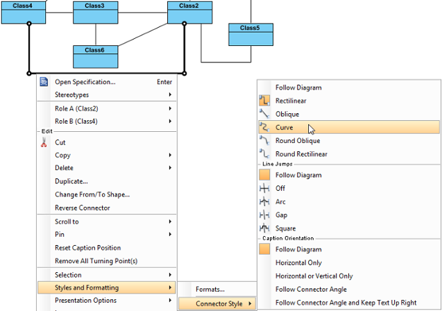
As a result, the connector is changed into the selected line style.
Line style options
| Name | Sample |
|---|---|
| Rectilinear | 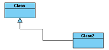 |
| Oblique | 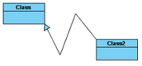 |
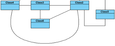
| Curve | 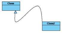 |
| Round Oblique | 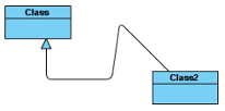 |
| Round Rectilinear | 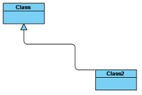 |
Setting diagram base line style
Beside the five styles mentioned above, there also have Follow Diagram feature, you don’t need to set the connector one by one if you want to change all connectors in the diagrams which defined as Follow Diagram.
To change the style of all lines on diagram, right click on the diagram background, select Connectors and one of five line style options from the pop-up menu.
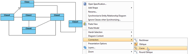
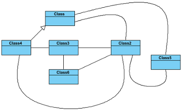
As a result, all lines on the diagram are changed into the selected line style.
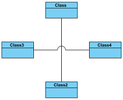
Setting line jumps options
As more diagram elements on your diagram, more miscellaneous connectors are overlapped with each other. It is impossible to explicate on those intersections which connector you indicate. The advantage of Line Jumps is making one of the two connectors different to another to indicate that which connector links with which diagram element clearly. Visual Paradigm provides four line jumps options to help you to distinguish connectors. Furthermore, the enhanced feature of line jumps in Visual Paradigm enables you to set different size of line jumps.
Setting connector line jumps options
To change the jumps option of a connector, right click on the connector, select Style and Formatting > Connector Style and then select an option under Line Jumps.

Note: The line jumps options are available only when two connectors are overlapped.
Line jump options
| Name | Sample |
|---|---|
| Off |  |
| Arc |  |
| Gap | 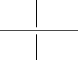 |
| Square |  |
Setting diagram base line jumps options
In addition to the 4 options mentioned above, Follow Diagram is another choice for altering the connectors. The main feature of Follow Diagram is, all connectors in the diagrams can be changed simultaneously instead of setting one by one.
Right click on the diagram’s background, select Connectors and select an option under Line Jumps from the pop-up menu.

Setting line jump for new project
- Select Window > Project Options from the toolbar to open the Project Options window.
- In the Project Options window, click the Diagramming page, open the Connector tab and select the Line Jumps style or select Off to disable it. At last, click OK to confirm the changes.
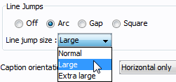
Setting different line jump size
You can enlarge the line jump size to make the selected line jump (or all line jumps) on the connector(s) more obvious. Furthermore, the size of line jump can be customized in either the current diagram or the future diagram. If you only want to set to the connectors of current diagram, right click on the diagram’s background, select Connectors and then a size option from the pop-up menu. Otherwise, if you want to set to the connectors of future diagram, set it through Project Options window. Three size are availabe for chooising. Normal is the standard size by default while extra large is the maximum size.
Setting line jump size for current diagram
- Right click on the diagram’s background, select Connectors and then a size option from the pop-up menu.
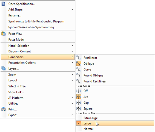
- The line jump(s) on the current diagram will turn into the size you selected.
Setting line jump size for future diagram
- Select Window > Project Options from the toolbar to open the Project Options window.
- In the Project Options window, click Diagramming page and open Connector tab.
- Under the Line Jumps section, check an line jump option and then select a line jump size option from Line jump size‘s drop-down menu.
Setting connector caption orientation
Visual Paradigm supports a number of ways of aligning connector caption, which apply on different modeling preferences. By default, the caption of a connector is aligned horizontal only, but you also can customize it to Follow Diagram, Horizontal Only, Horizontal or Vertical Only, Follow Connector Angle, and Follow Connector Angle and Keep Text Up Right. You can either customize it one by one or change all connectors in the diagram which defined Follow Diagram.
Setting connector caption orientation
To customize the caption orientation option of a connector, select the connector, right click and select Style and Formatting > Connector Style, and then select one out of four options under Caption Orientation.


Caption orientation options
| Name | Sample | >Description |
|---|---|---|
| Horizontal Only | 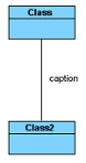 |
The caption of connector is aligned horizontally. |
| Horizontal or Vertical Only | 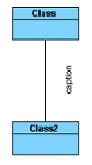 |
The caption of connector is aligned either horizontally or vertically, according to the connector. |
| Follow Connector Angle |  |
The caption of connector is aligned the diagonal angles of both shapes. |
| Follow Connector Angle and Keep Text Up Right | 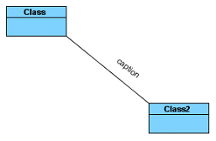 |
The caption of connector is aligned the diagonal angles of both shapes, but keeps top right. |
Setting diagram base connector caption direction
In addition to the 4 options mentioned above, Follow Diagram is another choice for altering the connector. The main feature of Follow Diagram is, all connectors in the diagrams can be changed simultaneously instead of setting one by one.
Right click on the diagram background, select Connectors and select one out of four options under Caption Orientation from the popup menu.

Setting connection point style
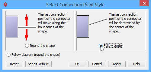
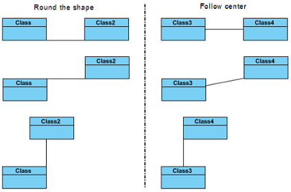
The connection point of a connector is used to connect from the original shape to the target shape using a connector. In Visual Paradigm, you can choose one of two kinds of connection point style: either Round the shape or Follow center for each shape. Round the shape allows you to set the last connection point of the connector moving along the boundaries of the original shape while Follow center refers the last connection point of the connector depends on the center of the original shape. The most attractive point of connection point style feature is that the animation of a connection point style will be playing repeatedly once you select the corresponding connection point style.
You can compare the differences of two kinds of connection point style shown as follows:
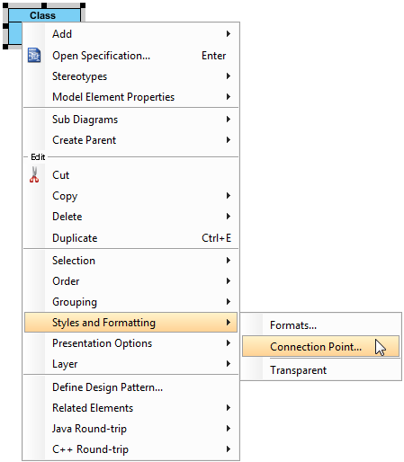
To set a connection point style:
- Right click on shape and select Styles and Formatting > Connection Point… from the pop-up menu.
- In the Select Connection Point Style dialog box, choose a connection point style option. Click OK button.