Open post

Deployment Diagram with Components

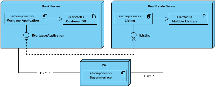
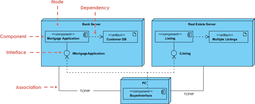
component is a code module. Component diagrams are physical analogs of class diagram. Deployment diagrams show the physical configurations of software and hardware. The following deployment diagram example shows the relationships among software and hardware components involved in real estate transactions.

The physical hardware is made up of nodes. Each component belongs on a node. Components are shown as rectangles with two tabs at the upper left.

Import into your Project

Posted by:

Open post

Hotel Reservation

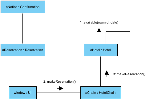
Here is a communication diagram example.

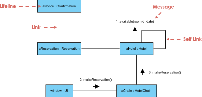
Communication diagrams are also interaction diagrams. They convey the same information as sequence diagrams, but they focus on object roles instead of the times that messages are sent. In a sequence diagram, object roles are the vertices and messages are the connecting links.

The object-role rectangles are labelled with either class or object names (or both). Class names are preceded by colons ( : ). Each message in a collaboration diagram has a sequence number. The top-level message is numbered 1. Messages at the same level (sent during the same call) have the same decimal prefix but suffixes of 1, 2, etc. according to when they occur.

Import into your Project

Posted by:

Open post

MVC Framework

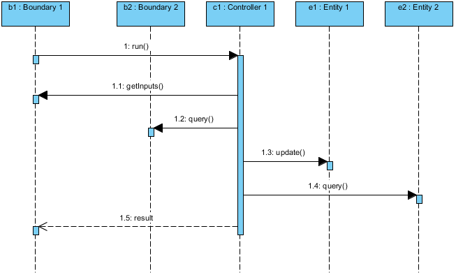
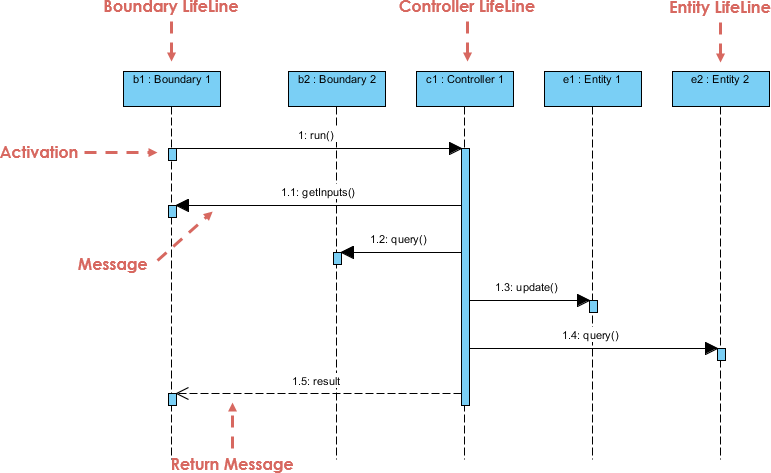
Here is a sequence diagram example.

  • Entities are objects representing system data: Customer, Product, Transaction, Cart, etc.
  • Boundaries are objects that interface with system actors: UserInterface, DataBaseGateway, ServerProxy, etc.
  • Controls are objects that mediate between boundaries and entities.

They orchestrate the execution of commands coming from the boundary by interacting with entity and boundary objects. Controls often correspond to use cases scenario and often represented by a sequence diagram.

Import into your Project

Posted by:

Posts navigation

1 2