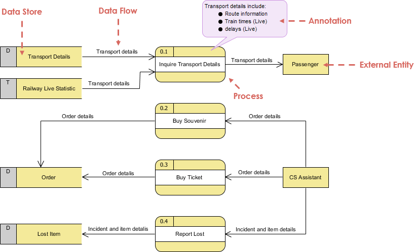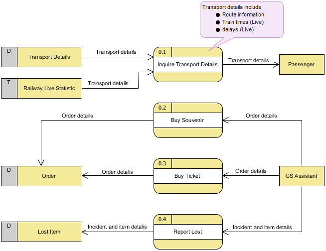
The DFD example here shows the level 1 DFD, which is the decomposition (i.e. break down) of the CS System process shown in the Context DFD. Read through the diagram and then we will introduce some of the key concepts based on this diagram. The CS System Data Flow Diagram example contains four processes, two external entities and four data stores. Although there is no design guidelines that governs the positioning of shapes in a Data Flow Diagram, we tend to put the processes in the middle and data stores and external entities on the sides to make it easier to comprehend.
Based on the diagram, we know that a Passenger can receive Transport details from the Inquiry Transport Details process, and the details are provided by the data stores Transport Details and Railway Live Statistic. While data stored in Transport Details are persistent data (indicated by the label "D"), data stored in Railway Live Statistic are transient data that are held for a short time (indicated by the label "T"). A callout shape is used to list out the kind of details that can be inquired by passenger.
Import into your Project
Open diagram in Visual Paradigm [?]Copy the URL below, paste it in the Open Project windows of Visual Paradigm and press Enter to open it |
Posted by: Brittany Shook
