Open post

Package Diagram – Ticket Selling System

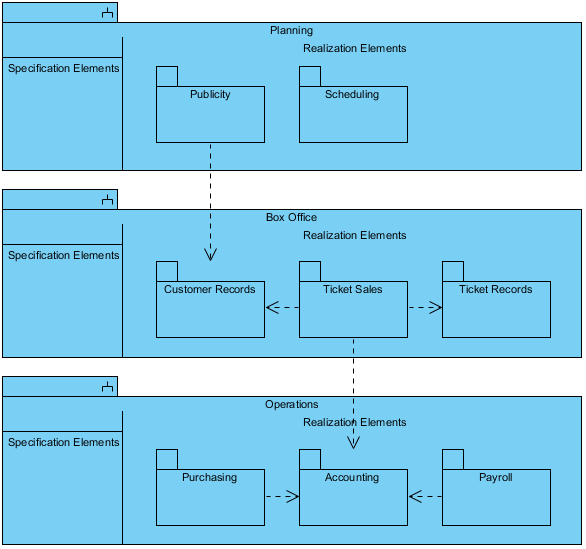
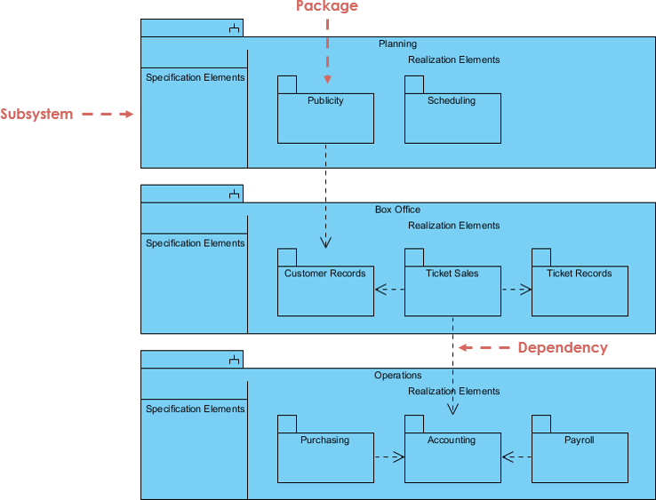
This is a Package Diagram example for ticket selling system.

A subsystem is another special package. It represents a portion of a system, with a crisp interface that can be implemented as a distinct component. Model management information is usually shown on class diagrams. This example shows the breakdown of the entire theater system into packages and their dependency relationships. The box office subsystem includes the previous examples in this chapter; the full system also includes theater operations and planning subsystems. Each subsystem consists of several packages.

Import into your Project

Posted by:

Open post

Deployment Diagram with Components

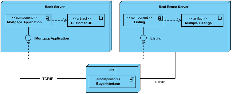
This is a Deployment Diagram example.

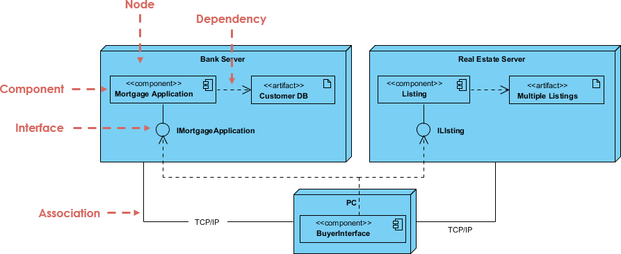
component is a code module. Component diagrams are physical analogs of class diagram. Deployment diagrams show the physical configurations of software and hardware. This deployment diagram shows the relationships among software and hardware components involved in real estate transactions.

The physical hardware is made up of nodes. Each component belongs on a node. Components are shown as rectangles with two tabs at the upper left.

Import into your Project
Open post

State Diagram Example – Phone Call

This is a UML state machine diagram example for telephone.

A state diagram is a graph whose node are state and whose directed arcs are transition between states which describes sequence caused by event sequences. A state diagram typically models the common behavior of a class

In this example, the phone line is idle at the start of a call. When the phone is removed from the hook, it emits a dial tone and can accept the dialling of digits. Upon entry a valid number, the phone system tries to connect the call and route to the proper destination. The connection can fail if the number or trunk are busy. If the connection is successful the called phone begins ringing. When put on hook again, the phone line will go back to idle.

Import into your Project
Open post

Hotel Reservation

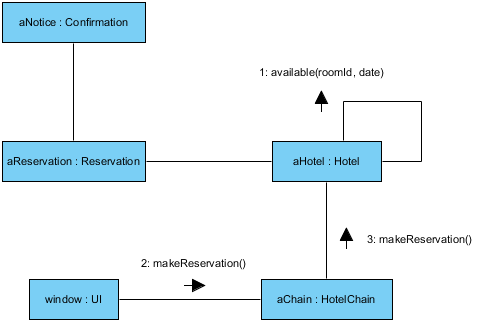
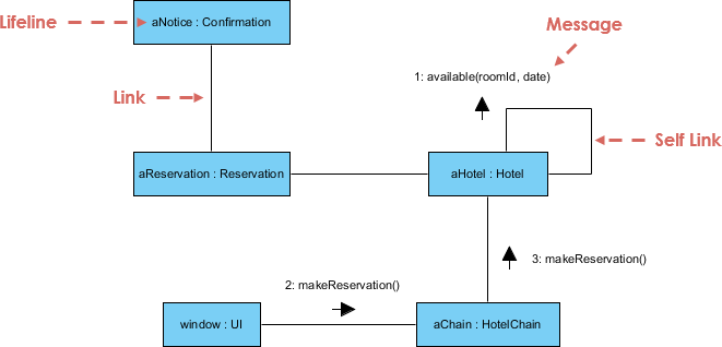
This is a Communication Diagram example for hotel reservation.

Communication diagrams are also interaction diagrams. They convey the same information as sequence diagrams, but they focus on object roles instead of the times that messages are sent. In a sequence diagram, object roles are the vertices and messages are the connecting links.

The object-role rectangles are labelled with either class or object names (or both). Class names are preceded by colons ( : ). Each message in a collaboration diagram has a sequence number. The top-level message is numbered 1. Messages at the same level (sent during the same call) have the same decimal prefix but suffixes of 1, 2, etc. according to when they occur.

Import into your Project
Open post

MVC Framework

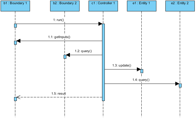
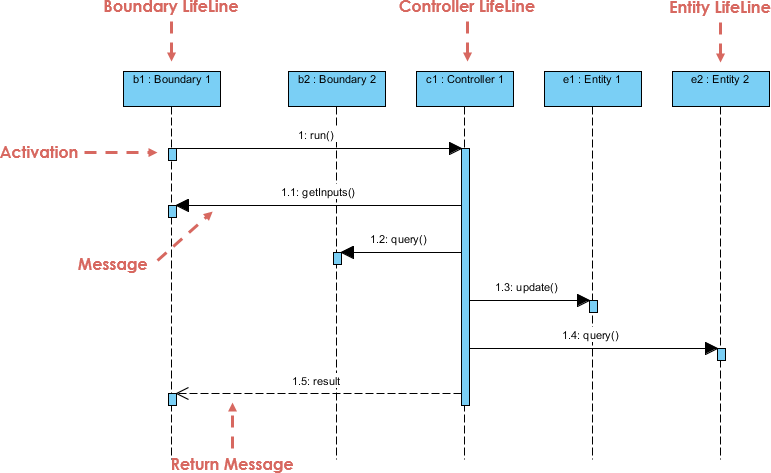
This is a UML sequence diagram example for MVC design pattern.

  • Entities are objects representing system data: Customer, Product, Transaction, Cart, etc.
  • Boundaries are objects that interface with system actors: UserInterface, DataBaseGateway, ServerProxy, etc.
  • Controls are objects that mediate between boundaries and entities.

They orchestrate the execution of commands coming from the boundary by interacting with entity and boundary objects. Controls often correspond to use cases scenario and often represented by a sequence diagram.

Import into your Project
Open post

Class Diagram – A Car

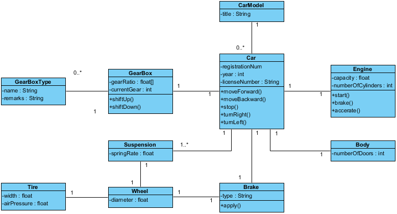
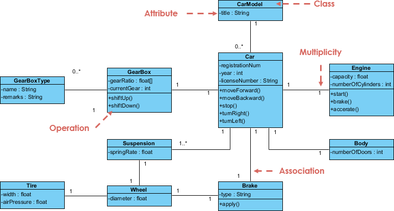
This is a UML class diagram example for car.

A car consists of different structural components, such as the engine, body, suspension, gearbox, etc. Each component in turn contains its own attributes and operations. For example, the engine has its capacity, and it can be started or stopped. We can represent the car with a class diagram. This is a class diagram example that shows a simplified structural model of a car in a class diagram.

Import into your Project

Posted by:

Open post

External System as Actor

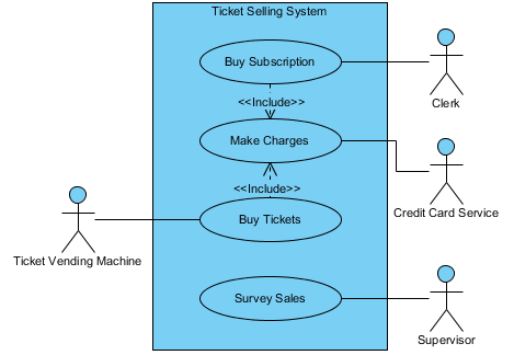
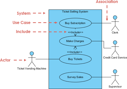
In this use case diagram example, actors include the clerk, supervisor, and Ticket Vending Machine. The Ticket Vending Machine is another system that accepts orders from a customer. The customer is not an actor in the box office application because the customer is not directly connected to the application. Use cases include buying tickets through the Ticket Vending Machine or the clerk, buying subscriptions (only through the clerk), and surveying total sales (at the request of the supervisor). Buying tickets and buying subscriptions include a common fragment—that is, making charges to the credit card service. (A complete description of a box office system would involve a number of other use cases, such as exchanging tickets and checking availability.)

Use cases can also be described at various levels of detail. They can be factored and described in terms of other, simpler use cases. A use case is implemented as a collaboration in the interaction view.

Import into your Project

Posted by:

Open post

Planning a Show

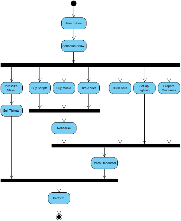
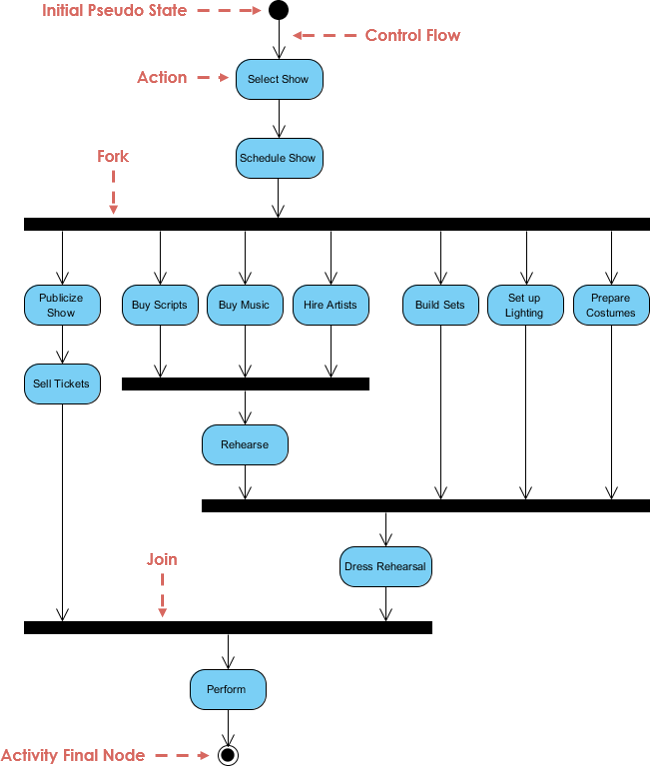
This activity diagram example shows an activity diagram for the theater office. This diagram shows the activities involved in planning a show.

  1. Arrows show sequential dependencies—for example, shows must be picked before they are scheduled.
  2. Heavy bars show forks or joins of control. For example, after the show is scheduled, the theater can begin to publicize it, buy scripts, hire artists, build sets, design lighting, and make costumes, all concurrently. Before rehearsal can begin, however, the scripts must be ordered and the artist must be hired.

A UML activity diagram is helpful in understanding the high-level execution behavior of a system, without getting involved in the internal details of message passing required by a collaboration diagram.

Import into your Project

Posted by:

Open post

Component Diagram Example – Web Store

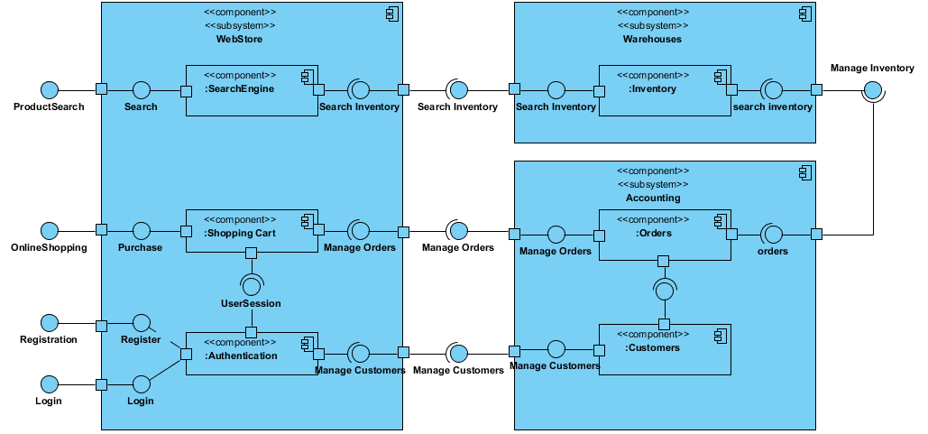
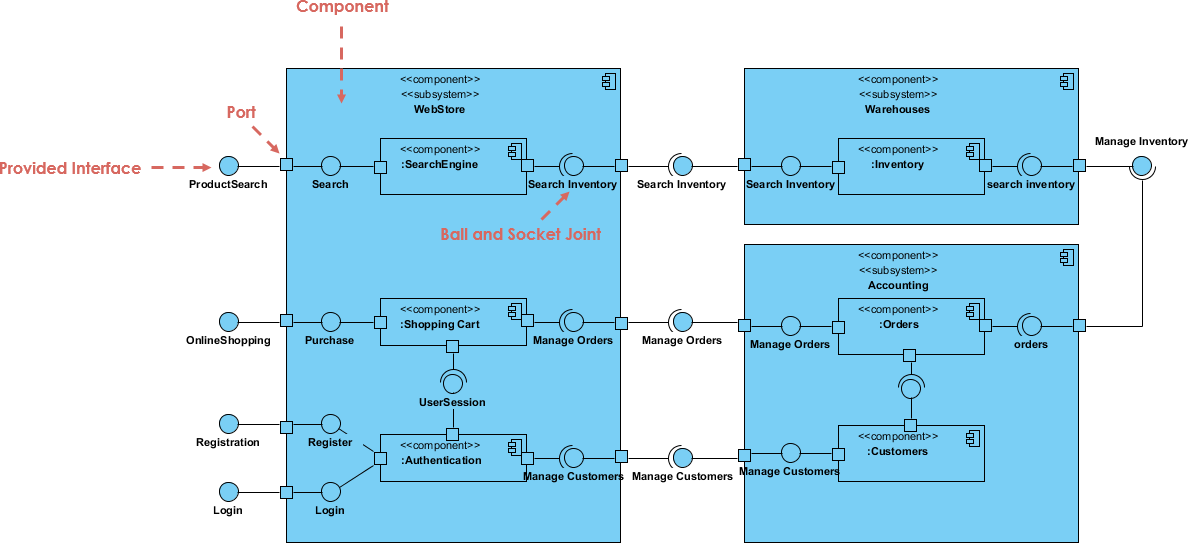
This is a Component Diagram example that shows the components in a web store.

Component diagram shows components, provided and required interfaces, ports, and relationships between them. This type of diagrams is used in Component-Based Development (CBD) to describe systems with Service-Oriented Architecture (SOA).

The following nodes and edges are typically drawn in a component diagram: component, interface, provided interface, required interface, class, port, connector, artifact, component realization, dependency, usage. These major elements are shown on the component diagram here.

Import into your Project

Posted by:

Open post

Visitor

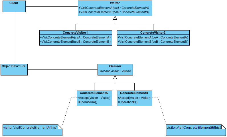
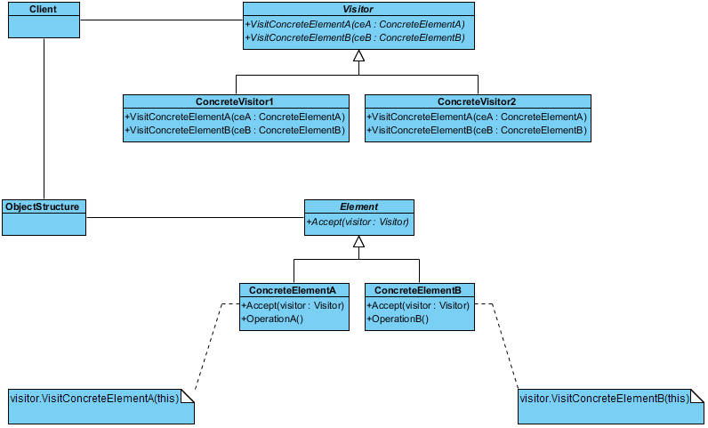
This is a class diagram example for the Visitor pattern.

Purpose

Allows for one or more operations to be applied to a set of objects at runtime, decoupling the operations from the object structure.

Use When

  • An object structure must have many unrelated operations performed upon it.
  • The object structure can't change but operations performed on it can.
  • Operations must be performed on the concrete classes of an object structure.
  • Exposing internal state or operations of the object structure is acceptable.
  • Operations should be able to operate on multiple object structures that implement the same interface sets.
Import into your Project

Posts navigation

1 2 3 12 13 14 15 16 17 18 45 46 47