Open post

Jukebox System

This deployment diagram example shows the deployment topology of a music Jukebox System and the relationship among the nodes: client PC, Web Repository and the Jukebox System. Each of the deployment nodes resides the component(s) which deployed to them.

Import into your Project
Open post

State / Condition lifeline vs General Value lifeline

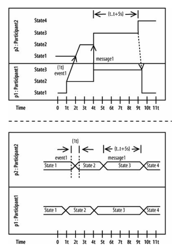
Here is a timing diagram example. The state / condition notation shows states as a list next to the relevant participant. A state-line is then needed to show what state a participant is in at a given time. Unfortunately, if a participant has many different states, then the amount of space needed to model a participant on the timing diagram will grow quickly.

The general value notation fixes this problem by removing the vertical list of different states. It places a participant's states directly at the point in time when the participant is in that state. Therefore, the state-line is no longer needed, and all of the states for a particular participant can be placed in a single line across the diagram.

Import into your Project
Open post

State / Condition Timeline

Here is a timing diagram example. Timing Diagram shows the behavior of the object(s) in a given period of time. Timing diagram is a special form of a sequence diagram. The differences between timing diagram and sequence diagram are the axes are reversed so that the time are increase from left to right and the lifelines are shown in separate compartments arranged vertically. Visual Paradigm supports both discrete timing and the general value lifeline style.

Import into your Project
Open post

Completing an Assignment

In this activity diagram example, we see swim lanes and the use of rectangles between the swim lanes to represent the flow of completing an assignment.  In addition there's an hour glass type symbol (two triangles, joined at their points), to represent an event related to the passage of time.

Import into your Project
Open post

Inspection

Here is an interaction overview diagram example. The Interaction Overview Diagram focuses on the overview of the flow of control of the interactions. It is a variant of the Activity Diagram where the nodes are the interactions or interaction occurrences. The Interaction Overview Diagram describes the interactions where messages and lifelines are hidden. You can link up the "real" diagrams and achieve high degree navigability between diagrams inside the Interaction Overview Diagram.

Import into your Project
Open post

A Car

Here is a composite structure diagram example. Composite structure diagram is a kind of UML diagram that visualizes the internal structure of a class or collaboration. It is a kind of component diagram mainly used in modeling a system at micro point-of-view.

Import into your Project
Open post

General Business System

Package diagram is used to simplify complex class diagrams, you can group classes into packages. A package is a collection of logically related UML elements. The package diagram example here is a business model in which the classes are grouped into packages. Packages appear as rectangles with small tabs at the top. The package name is on the tab or inside the rectangle. The dotted arrows are dependencies. One package depends on another if changes in the other could possibly force changes in the first.

Import into your Project
Open post

Use Case Example – ATM

Here is a use case diagram example for ATM. An automated teller machine (ATM) is banking subsystem that provides bank customers with access to financial transactions in a public space without the need for a cashier, clerk or bank teller.

Customer (actor) uses bank ATM to check balances of his/her bank accounts, deposit funds, withdraw cash and/or transfer funds (use cases). ATM Technician provides maintenance and repairs. All these use cases also involve Bank actor whether it is related to customer transactions or to the ATM servicing.

Import into your Project
Open post

Business Use Case Diagram Example – Airport

Here is a UML use case diagram example.

A primary purpose of the model of business use cases and actors is to describe how the business is used by its customers and partners. Activities that directly concern the customer, or partner, as well as supporting or managerial tasks that indirectly concern the external party can be presented. A use case diagram at its simplest is a representation of a user's interaction with the system that shows the relationship between the user and the different use cases in which the user is involved. Major elements of the business use case diagram are shown on the picture here. Note again, both business use case as well as business actor are not defined in UML standard, so you will either need to use some UML tool supporting those or create your own business modeling stereotypes.

Import into your Project

Posts navigation

1 2 3 42 43 44 45 46 47