Data Flow Diagrams (DFD) are used to show the movement of data within a business information system. It visualizes the transfer of data between processes, data stores and entities external to the system. Data flow diagrams often given us hints on how processes acting on the data store, such as:
- A data flow to a data store means update (create, update or delete)
- A data flow from a data store means retrieve or use
Objectives:
- Interrelate the relationship between a single process to a data store with CRUD matrix of database operations, (CREATE, READ, UPDATE, DELETE)
- Visualize what CRUD operations are required by the processes for acting on the data store in a matrix format
Main Steps:
- This STEPS Wizard assists you in developing a CRUD Chart that reflects the natures of data flows modeled in a DFD.
- You are required to draw a Data Flow Diagram, and then mark on the diagram the nature of data flows (C/R/U/D).
Finally, you will obtain a CRUD chart that presents how different processes use data within the system.

The figure above outlines how a CRUD Chart can be created from a DFD. In this article we will walk you through the steps in detail.
Try it in Visual Paradigm
Before we continue, if you are using Visual Paradigm you can click the button below to import this tutorial into Visual Paradigm and perform the steps in the form of a wizard.
Open this Wizard in Visual ParadigmStep 1: Draw a Data Flow Diagram
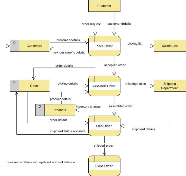
Draw a Data Flow Diagram (DFD) to model the movement of data within the target system. Complete the items below to finish this step:
- Identify the main processes in the information system
- Identify the external entities associated with the information system
- Identify the data stores
- Draw a Data Flow Diagram with these elements and connect them with data flow connectors.
Tips: What is a Data Flow Diagram?
Data Flow Diagrams (DFD) are used to show the movement of data within a business information system. It visualizes the transfer of data between processes, data stores and entities external to the system. System analyst uses Data Flow Diagram to:
- Identify major data involved in a system
- Identify the processes involved/required in processing these data
- Determine how data can be logically persisted
- Identify how data is being transformed across processes
Data Flow Diagram Symbols
There are mainly four symbols in a Data Flow Diagram.| Symbol | Description |
|---|---|
 |
|
|
|
|
|
|
To learn more about Data Flow Diagram (DFD), please read the article What is Data Flow Diagram
Step 2: Mark 'C', 'R', 'U' or 'D' on data flows
Indicate the nature of data flows, which are classified as:
- C - The data flow creates data in the data store connected
- R - The data flow receives data from the connected data store and forward it to another object on the diagram
- U - The data flow receives data from the connected source and updates the data in data store
- D - The data flow deletes data in data store
In order to complete this task, you need mark the data flows' types with the use of the Color Legend. Here are the steps to perform:
1. For each of the data flows that attach to a data store, determine its nature (either C, R, U or D).
2. Select the type from the Color Legend at the bottom right of the diagram.
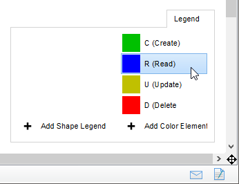
3. Click on the connector to apply. You should see the connector's color updated if success. If you want to update your choice, perform step 2 again.

4. Repeat steps 1 to 3 on the other data flows.
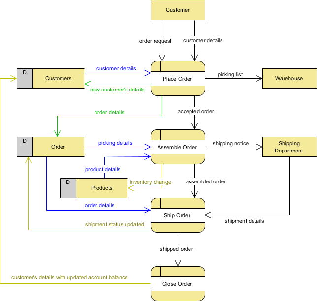
Step 3: Obtain the CRUD Chart
A CRUD Chart is generated based on assignment of C, R, U and D on the data flows. This step requires you to review the CRUD chart and make any necessary changes to the layout, like to resize the columns and rows. If you want to update the assignment of C, R, U and D, please re-perform step 2. This will cause a refresh of chart content. Note that any change you make directly in the chart will not be reflected back on the Data Flow Diagram.
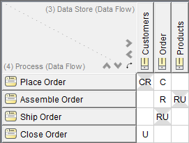
Ready to try?
Click the button below to import this tutorial into Visual Paradigm and start developing MVC Sequence Diagrams for your system. The wizard not only provides the steps and guidance but also automates the transition of data among steps.
Open this Wizard in Visual Paradigm
Import into your Project
Open diagram in Visual Paradigm [?]Copy the URL below, paste it in the Open Project windows of Visual Paradigm and press Enter to open it |

