
MVC, short for Model-View-Controller, is a well-known software architectural concept in software engineering. MVC promotes the decoupling of a context into three interconnected parts - business objects (model), view (representation of model data) and controller (performer of business operations). The concept of MVC is widely recognized and adopted in software industry. Many modern software frameworks are created based on MVC.
MVC is also widely used together with UML modeling. In a MVC Sequence Diagram, entity objects, boundary objects and the controllers are placed in three distinct parts. Readers can gain an overview of system interactions easily by reading the communications between the three layers of components.
Objectives
- Identify business entities for problem domain using conceptual ERD
- Identify business services required for the problem based in basic Create / Read / Update / Delete (CRUD) operations
- Elaborate the business services into MVC multiple layers of usage scenario using sequence diagrams as a blueprint for system design, wireframing and testing
Main Steps:
- This STEPS wizard provides a systematic approach to developing MVC Sequence Diagrams. You start off by understanding the problem background and building a conceptual ER model that describes the business objects important to the system.
- Then, identify the system activities/processes that create, read, update and delete those objects by forming a CRUD model.
- Finally elaborate the sequence diagram we generated for you based on the activities and processed identified.
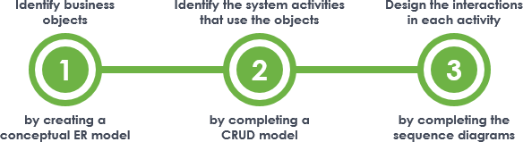
The figure above outlines how an MVC Sequence Diagram can be developed from scratch. In this article we will walk you through the steps in detail.
Try it in Visual Paradigm
Before we continue, if you are using Visual Paradigm you can click the button below to import this tutorial into Visual Paradigm and perform the steps in the form of a wizard.
Open this Wizard in Visual ParadigmStep 1: Identify business objects
Draw a conceptual Entity Relationship Diagram (ERD) to model the business objects within the scope of the target system and the inter-relationships among these objects. When you construct the model, keep in mind that you are modeling business objects, not any database table to use in physical database construction.
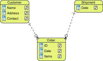
The figure above gives an example of such an ERD. The table below provides some examples of business objects.
| System | Business Objects |
|---|---|
| ATM |
|
| Library Management System |
|
Tips: What is a ‘Conceptual’ ERD?
An ER model is typically drawn at up to three levels of abstraction:
- Conceptual ERD / Conceptual data model
- Logical ERD / Logical data model
- Physical ERD / Physical data model
While all the three levels of ER model contain entities with attributes and relationships, they differ in the purposes they are created for and the audiences they are meant to target.
A general understanding to the three data models is that business analyst uses conceptual and logical model to model the business objects exist in the system, while database designer or database engineer elaborates the conceptual and logical ER model to produce the physical model that presents the physical database structure ready for database creation. The table below shows the difference between the three data models.
Conceptual ERD models the business objects that should exist in a system and the relationships between them. A conceptual ERD is developed to present an overall picture of the system by recognizing the business objects involved. It defines what entities exist, NOT which tables. For example, 'many to many' tables may exist in logical or physical data model but they are just shown as a relationship with no cardinality under the conceptual data model.
To learn more about ER Diagram, database design and the three kinds of data model, please read the article What is Entity Relationship Diagram (ERD).
Step 2: Identify the system activities that use the objects
Now that you have identified a set of business objects. In this step, you are required to find out how these objects will be used by the developing system - Are the objects created by the system, and if so, when? When will they be retrieved, modified or deleted by the system?
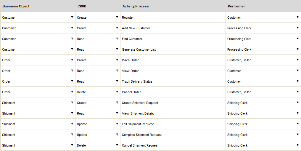
Now, find out the major system activities or processes that (will) create, read, update and delete those business objects. For each of the activities / processes identified, create a table row and enter the information below.
- Business Object: The business object being assessed.
- CRUD: Whether the activity / process will create, read, update or delete the business object.
- Activity / Process: The system activity or process that creates, reads, updates or deletes the business object.
- Performer: The person (role) or other business entities who creates, reads, updates or deletes the business object through the activity / process chosen. If necessary, you may include multiple performers here.
The figure below shows an example of such a table.
When you fill in the table, you may discover business objects that were not found before. Simply re-visit step 1 by updating the ERD with any new business objects found. If you are running this tutorial in our STEPS Wizard in Visual Paradigm, by re-completing step 1 we will update the listing of business objects available for selection in this step.
Notes:
- Do not include business objects that will not be created/read/updated/deleted by the system.
- Do not include any operation that will not be supported by the system. For instance, if the object "Account" will never be deleted by any means, don't add a row for "Delete".
- It is possible for a business object to be created, read, updated or deleted by more than one activities / processes. In such case, create multiple rows.
Step 3: Design the interactions in each activity
The major system activities through which business objects are created, read, updated and deleted are identified. In this step, we will take a closer look at the interactions involved in these activities. The result will be a set of MVC Sequence Diagrams that model the interactions.
If you are running this tutorial in our STEPS Wizard in Visual Paradigm, a set of initial Sequence Diagram templates have been automatically generated for each of the activities/processes identified. Each diagram template contains the following elements:
- Actors generated from the performers
- An <<entity>> lifeline generated from the business object
- A <<boundary>> lifeline named 'View'
- A <<controller>> lifeline named 'Controller'
- A Diagram name is automatically generate based on the activity, performer(s), ….
Complete the diagrams to model the MVC level interactions between the performers and the system. Here are some steps that you can follow to complete a diagram:
- Add sequence messages between lifelines to model the communication between lifelines
- Add additional lifeline to model the units that take part in the interaction. (E.g. Utility, external party, etc)
- Rename the View and Controller lifeline to something specific (e.g. 'Login Page' instead of 'View', 'MainController' instead of 'Controller')
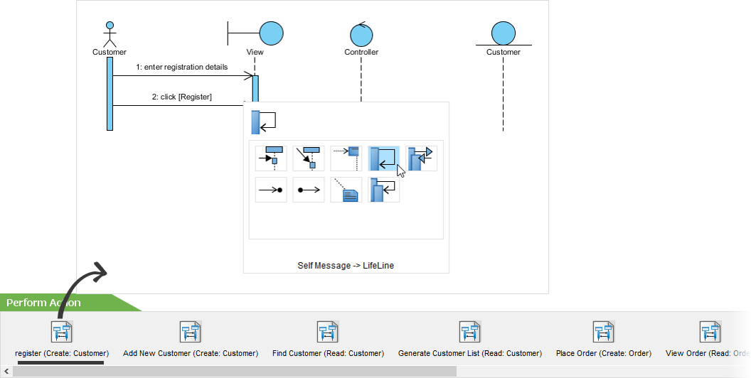
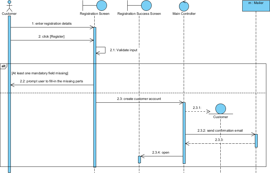
The figure below shows an MVC Sequence Diagram finished.
Ready to try?
Click the button below to import this tutorial into Visual Paradigm and start developing MVC Sequence Diagrams for your system. The wizard not only provides the steps and guidance but also automates the transition of data among steps.
Open this Wizard in Visual Paradigm
Import into your Project
Open diagram in Visual Paradigm [?]Copy the URL below, paste it in the Open Project windows of Visual Paradigm and press Enter to open it |