Open post

Abstract Factory

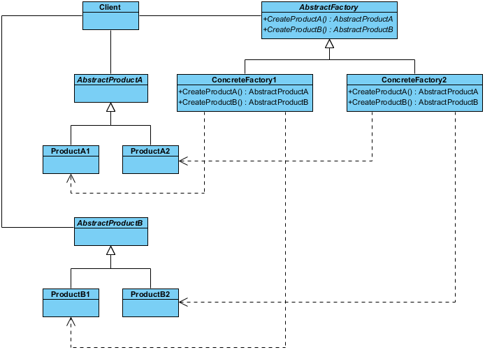
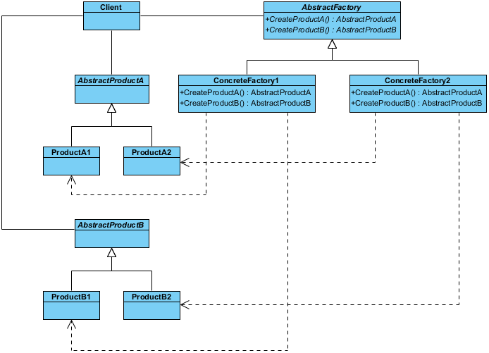
This is a UML class diagram example for the abstract factory design pattern.

Purpose

Provide an interface that delegates creation calls to one or more concrete classes in order to deliver specific objects.

Use When

  • The creation of objects should be independent of the system utilizing them.
  • Systems should be capable of using multiple families of objects.
  • Families of objects must be used together.
  • Libraries must be published without exposing implementation details.
  • Concrete classes should be decoupled from clients.
Import into your Project
Open post

Factory Method

This is a UML class diagram for the factory method design pattern.

Purpose

Exposes a method for creating objects, allowing subclasses to control the actual creation process.

Use When

  • A class will not know what classes it will be required to create.
  • Subclasses may specify what objects should be created.
  • Parent classes wish to defer creation to their subclasses.
Import into your Project
Open post

Catalog

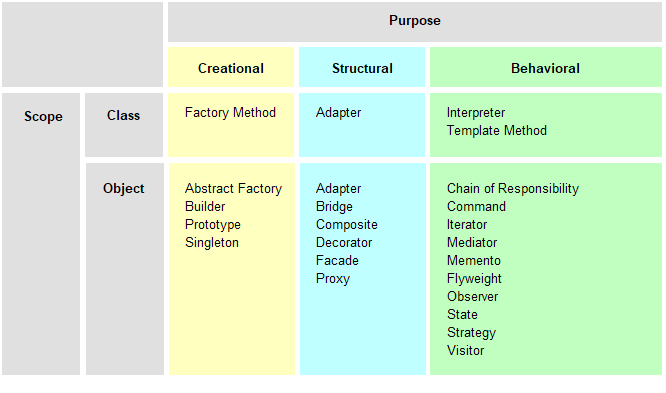
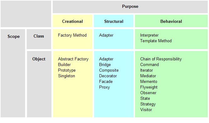
Design patterns are solutions to software reuse for software development in real-world. A pattern is the outline of a reusable solution to a general problem encountered in a particular context. Studying patterns is an effective way to learn from the experience of others. They contain a solution that has been proven to effectively solve the problem in the indicated context. The 23 Gang of Four (GoF) patterns are generally considered the foundation for all other design patterns. They are categorized in three groups: Creational, Structural, and Behavioural.

- Creational Patterns: Used to construct objects such that they can be decoupled from their implementing system.
- Structural Patterns: Used to form large object structures between many disparate objects.
- Behavioral Patterns: Used to manage algorithms, relationships, and responsibilities between objects.

Import into your Project
Open post

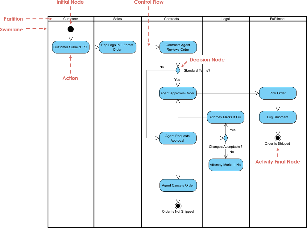
Swimlane for Order Fulfilment

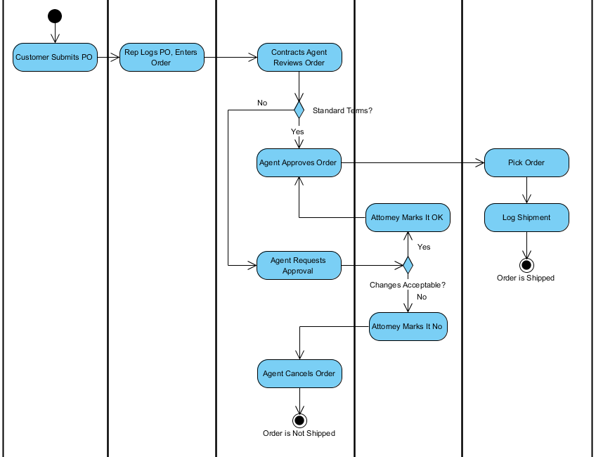
This is a UML activity diagram example for order fulfillment.

A swimlane activity diagram groups the activities into swimlanes columns that contain all of the activities which fit into the category represented by that swimlane.  Swimlanes can represent many categories of information such as actors which perform the activities (i.e., role or department), the stage of the process in which the activity takes place, or whatever else the creator of the document feels should be emphasized and communicated by the swimlane diagram.  The term swimlane was adopted due to the visual similarity between the horizontal rows of the diagram to that of the swimlanes found within a swiming pool.

Import into your Project
Open post

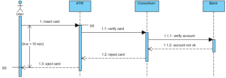
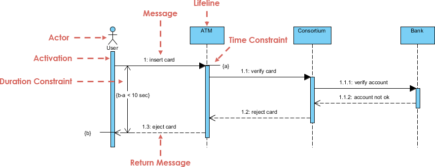
ATM Time Constraint

This sequence diagram example shows a simple scenario for the use of an automatic teller machine. In this scenario, the system rejects the card. For the customer this transaction is simple: he inserts the card and the card is rejected. For the system, several actions are necessary. A constraint specifies 10 seconds as the maximum acceptable time interval for the transaction.

Import into your Project
Open post

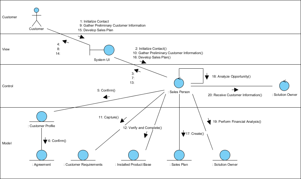
Financial Analysis

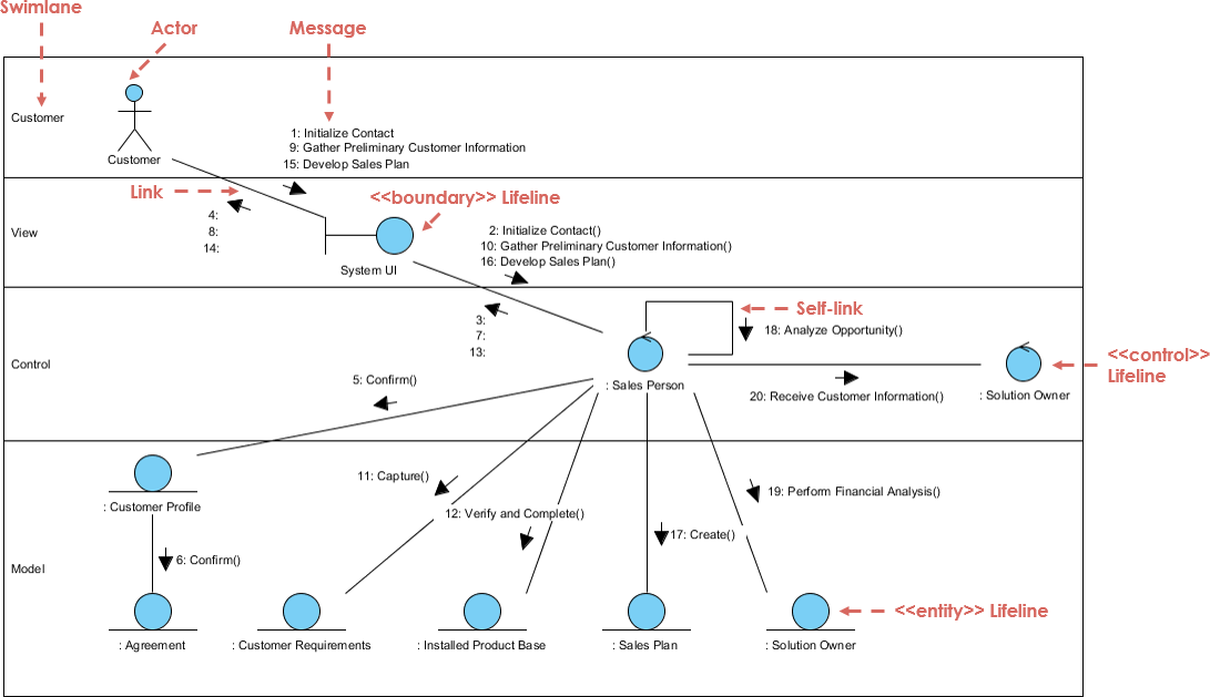
This is a Communication Diagram for financial analysis.

A business collaboration diagram documents how business workers and business objects actually interact to perform a business function. Collaboration diagrams show the messages exchanged between business workers and business entities during the course of realizing a business use case (implementing a business process). Collaboration diagrams can clearly indicate areas of improvements by visually showing business workers being responsible for a large number of tasks.

This example shows a view of participating business workers (Sales Person, Solution Owner) and business entities (Customer Profile, Sales Plan, etc) in a Proposal process in an MVC 3 layered structure.

Import into your Project
Open post

Relationships between Activates and Business Entities

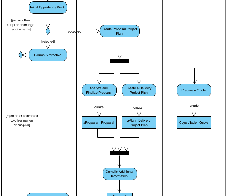
This is an Activity Diagram example that shows the relationships between activities and business entities.

Besides areas of responsibilities and specific activities, business activity diagrams can also show business entities being manipulated in the activities.

  • Business entities represent objects that are either created, updated or used during the course of the business activity.
  • Things like customer profile, paycheck, order, etc.

Note That:

If you model the business with the goal of eliciting better system requirements, some of these business entities will become analysis classes in your system design, in essence reusing the business artifacts in the design of the system.

This diagram shows the business entities (aProposal, a Quote, aPlan) and their states (created/complete).

Import into your Project
Open post

Swinlane Proposal Process

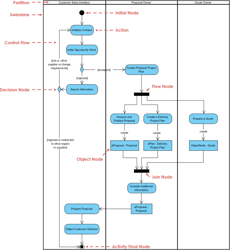
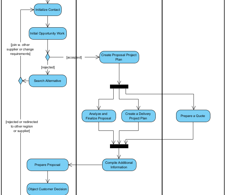
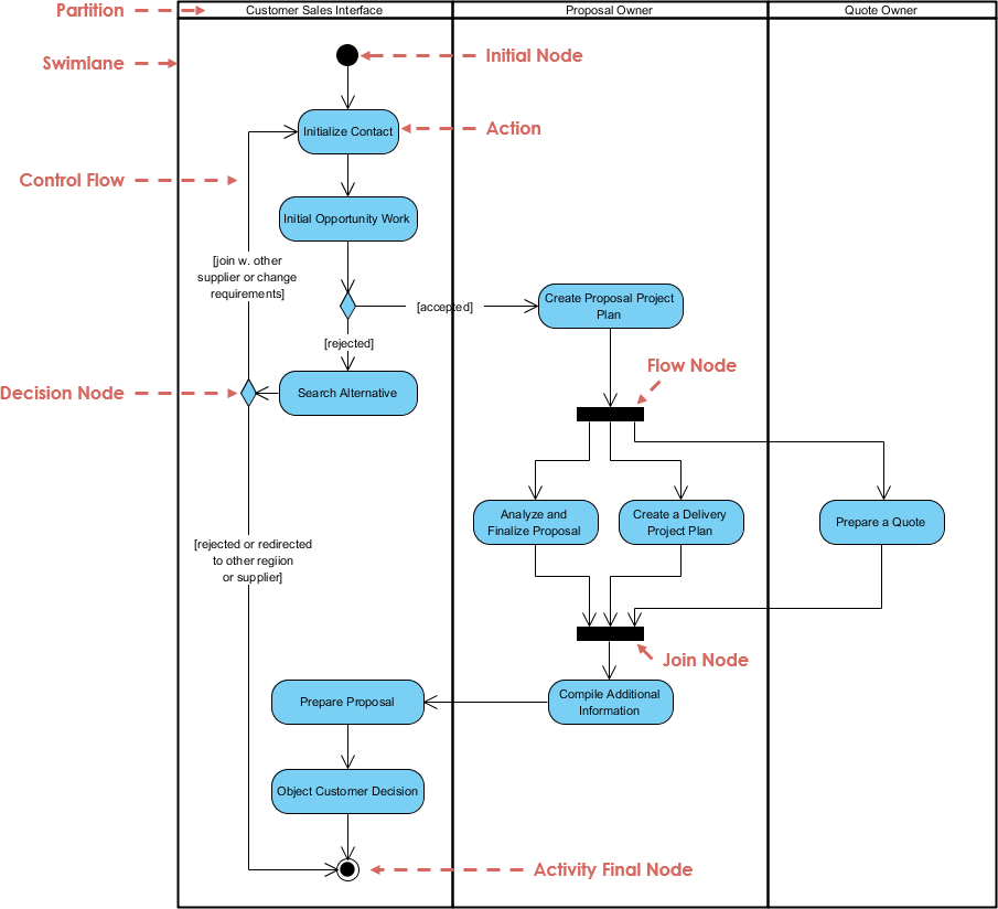
This is an activity diagram example for the proposal process.

Activity diagrams also describe the roles and areas of responsibilities in the business – in other words who is responsible for doing what in the business. Roles and areas of responsibilities are documented as columns (UML swimlanes) in the activity diagram. Swimlanes show which business workers participate in the realization of the workflow

This activity diagram documenting how the business performs a Proposal process, with three areas of responsibilities (Customer Sales Interface, Proposal Owner, and Quote Owner)

Import into your Project
Open post

Classes and Packages Constraints

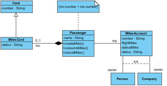
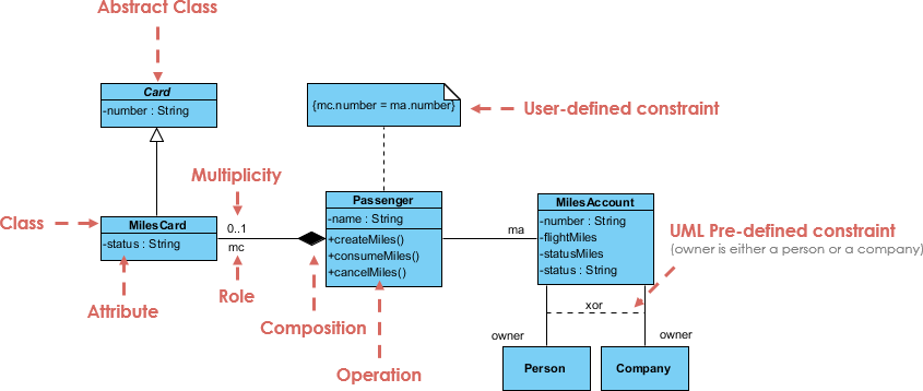
This is a simple class diagram example that shows the use of constraints.

Class or Package constraints may apply to one or more elements. There are no prescribed language and OCL is often used in the UML 2.0 specification. We can also use natural language instead.

Import into your Project
Open post

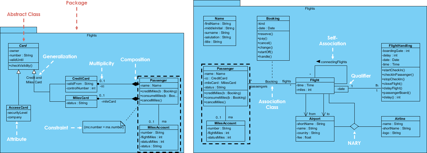
Class in a Package (Airline)

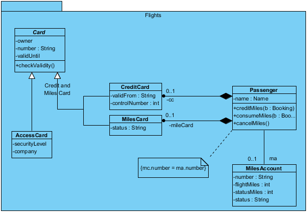
This class diagram example describes the structural relationship of an airline information system.

The Passenger and milesAccount Classes appear in both class diagrams here (with the same name). While the one in the right is the master view, and the other one on the left is the auxiliary view. We often don’t want to include all details (all domain classes) in a single class diagram. Perhaps, we can include only the essential classes initially in the class diagram and we then elaborate them in more detail by associating more classes in other diagram. And yet they are inter-related and will be kept consistent among them when any one view of the element has been updated.

Import into your Project

Posts navigation

1 2 3 15 16 17 18 19 20 21 45 46 47