ERD, short form for Entity Relationship diagram is a kind of diagram for presenting the properties as well as the relationships between data or participants. Database designer uses ERD to model physical structure of a relational database, while business analyst uses ERD to model the data that is logically required or produced by processes. In this page you will learn how to draw entity, how to add column and how to create relationship between entities.
Creating Entity Relationship Diagram
- Select Diagram > New from the application toolbar.
- In the New Diagram window, select Entity Relationship Diagram.
- Click Next.
- Enter the diagram name and description. The Location field enables you to select a model to store the diagram.
- Click OK.
- This creates an Entity Relationship Diagram. At the top right corner of the diagram, select the Data Model. All entities created in this diagram will be set to the chosen data model. And note that only entities in physical model will be included in generating database/DDL.
Drawing an entity
To draw an entity, select ![]() from the diagram toolbar and then click on the diagram. An entity will be created.
from the diagram toolbar and then click on the diagram. An entity will be created.
![]()
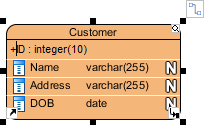
Adding column into entity
To add column into entity:
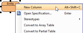
- Right click ont he entity and select New Column from the popup menu.
- A column is added. Enter its name in the pattern COL_NAME : COL_TYPE where COL_TYPE is the data type of column.
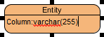
- Press Enter to confirm.
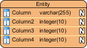
- Now, you can repeat step 2 and 3 to add more columns. When finished editing, press Esc to confirm.
Modeling MySQL ‘Set type’
SET columns in MySQL allows the definition of columns that can contain a given set of values. In Visual Paradigm you can model a set type with the steps below:
- Add a column into the entity.
- Right click on the column and select Open Specification… from the popup menu.
- Select varchar to be the Type of column.
- Enter the definition statement in the User type field, in pattern SET(‘a’,’b’,’c’, …) where ‘a‘, ‘b‘, ‘c‘… are the allowed values of this column.
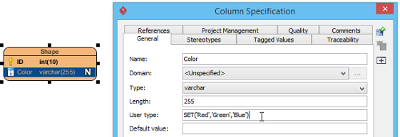
Note: The User type field is only available when the DBMS selected in database configuration supports the definition of user type. E.g. MySQL. - Click OK to confirm. Note that the definition will also be effective in database and DDL exporting.
Specifying primary key
There are several ways you can take to specify a column as a primary key. When inline editing, you can type + before the column name to indicate that the column is a primary key column.
Alternatively, right click on a column and select Include in Primary Key to set the column as primary key or include it as part of a composite key. Finally, you can also find and check the Include in Primary Key option in the Column Specification window. To open the window, right click on a column and select Open Specification… from the popup menu.
Clustered and non-clustered primary key
The use of clustered primary key may make the querying of data more efficient. To make a primary key of an entity a clustered/non-clustered primary key:
- Right click on that entity and select Open Specification… from the popup menu.
- Open the Columns tab.
- Select Clustered/Non-Clustered for Primary key clustered.
- Click OK.
Hiding nullable icons in ERD
In case you want to hide the nullable icon (as represented by symbol N) in ERD, you can follow the steps below: Right click on the diagram > Presentation Options > Entity Columns Display Options> Column Constraints Presentation Option> uncheck Show Nullable.
Selecting all columns in an entity
To select all columns within an entity, select any column first, and then press Ctrl-A to select the rest.
Working with relationships
Creating an entity with relationship
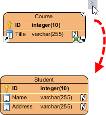
Relationship shows how the entities are related to each other. You can create a related entity by performing the steps below:
- Move your mouse pointer over the source entity.
- Press on the Resource Catalog button and drag it out.
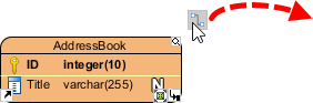
- Release the mouse button at the place where you want the entity to be created.
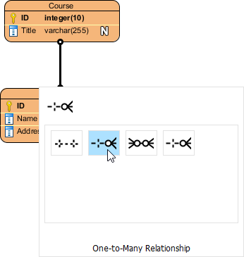
- In Resource Catalog, select the kind of relationship to be created. If you want to create an entity with a one-to-many relationship, select One-to-Many Relationship -> Entity.
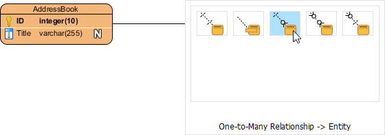
- You should see the entity now and it is connected to the source entity. Enter its name and press Enter to confirm editing.
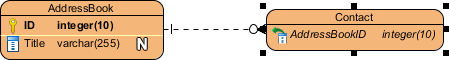
Connecting to existing entity
To connect to en existing entity:
- Move your mouse pointer over the source shape.
- Press on the Resource Catalog button and drag it out.
- Release the mouse button at the target entity.
- In Resource Catalog, select the kind of relationship to be created.
The entities are now connected with the relationship you chose.
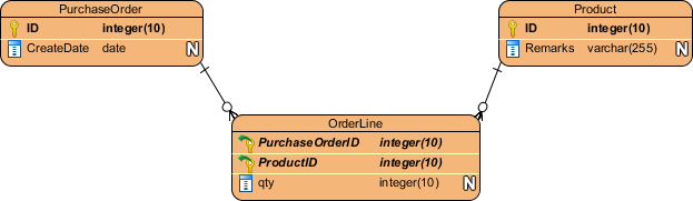
Linked entity in many-to-many relationship
When you create a many-to-many relationship, a linked entity will be created, with two one-to-many relationships connected to it from the source entities.
Identifying and non-identifying relationships
There are two types of relationships – identifying and non-identifying.
Identifying relationship specifies the part-of-whole relationship. It means that the child instance cannot exist without the parent instance. Once the parent instance is destroyed, the child instance becomes meaningless.
Non-identifying relationship implies weak dependency relationship between parent and child entities. There are two kinds of non-identifying relationships, including optional and mandatory. The necessity of the parent entity is “exactly one” and “zero or one” in the mandatory and optional non-identifying relationship respectively.