A state machine involves a number of states as well as the transition of states. You can generate source code for a state machine by first creating a controller class, then create sub-state machine diagram from the controller class, model the state machine. In this chapter, you will see how to model a state machine readily for code generation. For the steps of code generation, read the next chapter.
Step 1 – Modeling controller class
A controller class is a class that is used for controlling and managing the activities within a use case. It also manage the states within the use case or the system.
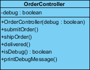
You can create a controller class by selecting Class from diagram toolbar and click on the diagram. Name the class properly to represent the nature of controller class. Very often, people name controller class as SomethingController where the Something refers to a use case or the model that the controller need to manage. For example, a PhoneController is for controlling operations of a telephone and managing its states like waiting, dialing, etc.
You can add attributes to the class by right clicking on it and selecting Add > Attribute from the popup menu. Attributes defined will be generated to code. However, you do NOT need to add attributes for states nor attributes for remembering states. Everything about states will be managed by the state machine in state machine diagram.
Add operations to the class by right clicking on it and selecting Add > Operation from the popup menu. There should be operations that may update the state.
Step 2 – Modeling state machine
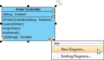
You need to create a sub state machine diagram from the controller and model the state machine there. To create a sub state machine diagram, move the mouse pointer over the controller class, click on the resource icon at bottom right corner and select New Diagram… from the popup menu. In the New Diagram window, select State Machine Diagram. Click Next and then OK to confirm.
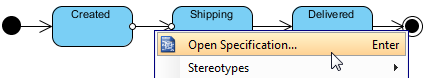
In the state machine diagram, draw the states as well as the transition of states. Since the states will be generated to source code, you are adviced to consider the naming convention of the programming language you want to generate when naming states.
![]()
You do not need to name the transitions as we will assign operations to them. But if you want you can do this. It will not affect the code that will be generated.
Step 3 – Assigning operations to transitions
A transition is a relationship between two states, representing the update of states. Previously you have defined operations in controller class. Now, you need to assign those operations to the transitions to indicate the cause of state change. To assign an operation to transition:
- Right click on a transition and select Open Specification… from the popup menu.
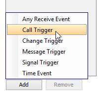
- Open the Triggers tab.
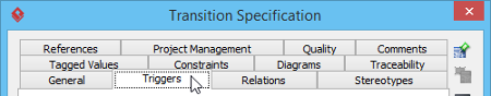
- Click Add and select Call Trigger from the popup menu.
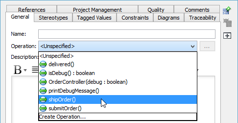
- In the General tab, specify the operation from the Operation drop down menu.
Repeat the steps to assign operations to all transitions.
Step 4 – Specifying method body for the entry/exit of state
You can specify the invokcation of method call when entering and exiting a state by updating the Entry properties of state. To do this:
- Right click on the state and select Open Specification… from the popup menu.
- Click on the drop down menu next to the Entry field, then select Create Activity….
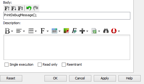
- In the specification, fill in the Body field by entering the methods to invoke. Click OK to confirm.
- Repeat the steps on Exit.
Step 5 – Specifying method body for operation
Part of the method body of operations being assigned to transitions can be defined by editing the Exit property of a transition. To do this:
- Right click on the transition where operation was assigned.
- Click on the drop down menu next to the Exit field, then select Create Activity….
- Fill in the Body. Click OK to confirm.
- Click OK to confirm and go back to diagram.