Component diagram is a kind of UML diagram. shows the physical aspect of an object-oriented software system. It illustrates the architectures of the software components and dependencies between them.
Creating component diagram
Perform the steps below to create a UML component diagram in Visual Paradigm.
- Select Diagram > New from the application toolbar.
- In the New Diagram window, select Component Diagram.
- Click Next.
- Enter the diagram name and description. The Location field enables you to select a model to store the diagram.
- Click OK.
Creating component
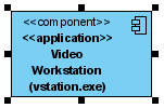
To create component in component diagram, click Component on the diagram toolbar and then click on the diagram.
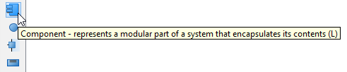
A component will be created.
![]()
Assigning stereotypes
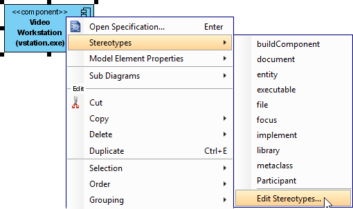
Right click on the package and select Stereotypes > Edit Stereotypes… from the pop-up menu.
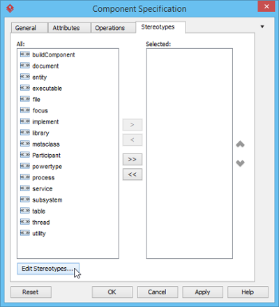
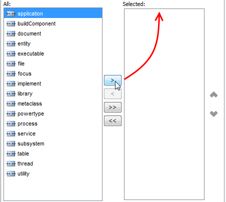
When the Component Specification window is opened, with the Stereotypes tab selected. The list on the left shows the selectable stereotypes.
If the stereotype you want to use is not on the list, click Edit Stereotypes… button.
Click Add… button in the Configure Stereotypes window.
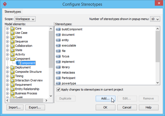
Name the stereotype (e.g. application) in the Stereotype Specification window and then click OK button to close it. Click OK button in the Configure Stereotypes window. The added stereotype will then be shown on the list in the Component Specification window. Select it and click Add Selectedbutton. Finally, click OK button to confirm.
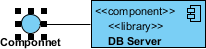
Close the specification window. Stereotypes will be applied to the package.
Creating provided interface
To create provided interface for a component:
- Move your mouse pointer over the source component.
- Press on the Resource Catalog button and drag it out.
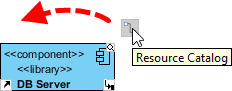
- Release the mouse button at the place where you want the interface to be created.
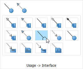
- Select Realization -> Interface from Resource Catalog.
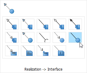
- A new interface will be created and is connected to the source component. Enter its name and press Enter to confirm editing.
Creating required interface
To create required interface for a component, just follow the steps described above for creating provided interface, but change to select Usage-> Interface in Resource Catalog.
Creating dependency
To create dependency, click Dependency on the diagram toolbar.
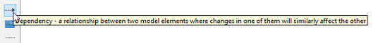
Drag from the source shape, move the mouse over the target shape and then release the mouse button to create the dependency.
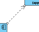
Continue to complete the diagram.

Showing/hiding attributes in component
Per diagram
You can add attributes to a component. To show/hide the attributes for all components in a diagram:
- Right click on the background of the component diagram.
- Select Presentation Options > Component Display Options from the popup menu.
- Select/De-select Show Attributes to cause attributes to be shown or hidden.
Per component
You can add attributes to a component. To show/hide the attributes for a specific component:
- Right click on the desired component.
- Select Presentation Options > Show Attributes Mode from the popup menu.
- Select Follow Diagram/Show All/Hide All/Customized… from the popup menu. If you have selected the Customized option, you can select the specific attribute(s) to be shown or hidden.
Showing/hiding operations in component
Per diagram
You can add operations to a component. To show/hide the operations for all components in a diagram:
- Right click on the background of the component diagram.
- Select Presentation Options > Component Display Options from the popup menu.
- Select/De-select Show Operations to cause attributes to be shown or hidden.
Per component
You can add operations to a component. To show/hide the operations for a specific component:
- Right click on the desired component.
- Select Presentation Options > Show Operations Mode from the popup menu.
- Select Follow Diagram/Show All/Hide All/Customized… from the popup menu. If you have selected the Customized option, you can select the specific operation(s) to be shown or hidden.