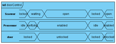
Timing diagram is a kind of UML diagram that shows time, event, space and signal for real-time and distributed system.
Creating timing diagram
Perform the steps below to create a UML timing diagram in Visual Paradigm.
- Select Diagram > New from the application toolbar.
- In the New Diagram window, select Timing Diagram.
- Click Next.
- Enter the diagram name and description. The Location field enables you to select a model to store the diagram.
- Click OK.
Creating timing frame
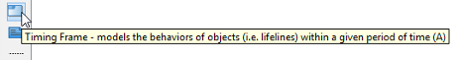
To create timing frame in a timing diagram, click Timing Frame on the diagram toolbar and then click on the diagram.
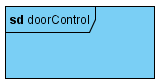
Double click on the top left corner of the frame to rename it.
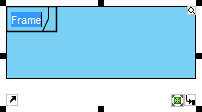
The name of a timing frame is usually preceded by the sd keyword.
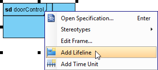
Adding lifeline to frame
To add lifeline to a timing frame, right-click the frame and select Add Lifeline from the pop-up menu.
Double-click on the name of the lifeline to rename it.
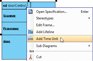
Adding time unit to frame
To add time unit to a timing frame, right-click the frame and select Add Time Unit from the pop-up menu.
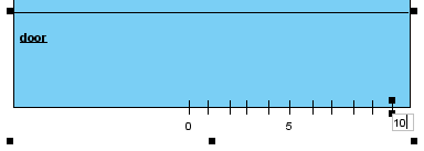
Repeat the step to add as many as time units you need. Double-click on a time unit to rename it.
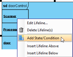
Adding state/condition to lifeline
To add state/condition to a lifeline, right-click the lifeline and select Add State/Condition from the pop-up menu.
Double click on the name of the state/condition to rename it.
Dragging time instance
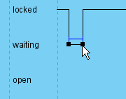
Move your mouse pointer over the line segment of a time instance, click and drag it.
Release the mouse button when reached the target state/condition.
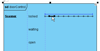
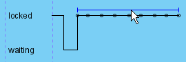
You can also move a group of time instances that are at the same state/condition. Mouse over the time instances and you will see a blue line above them, click and drag on the blue line.
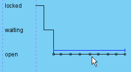
Release the mouse button when reached the target state/condition. The group of time instances is moved at once.
Adding time messages to frame
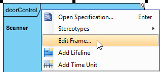
To add time messages to frame, right-click the timing frame and select Edit Frame… from the pop-up menu.
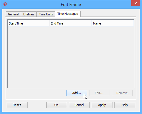
In the Edit Frame window, open the Time Messages tab and click Add… button.
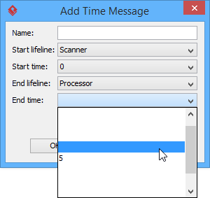
When the Add Time Message window pops out, enter name and select the start lifeline, start time, end lifeline and end time for this time message. Note that as time units may be unnamed, when selecting start/end time you should check the relative position of the time unit in the list.
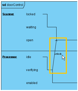
The time message is shown on the frame.
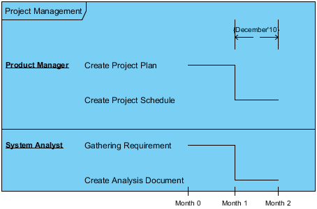
Adding duration constraint
Duration constraint is used to show the duration limitation of a particular lifeline over a period of time.
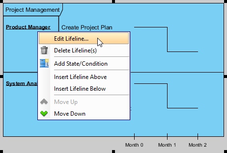
- To set the duration constraints of a lifeline, right-click on the lifeline and select Edit Lifeline… from the pop-up menu.
- In the Duration Constraints tab, click on the Add… button. In the Add Duration Constraint window, select the appropriate Start timeand End time from the drop down menu. Fill in the duration constraint of the selected time on the Constraint field. Click on the OK button to close the window.
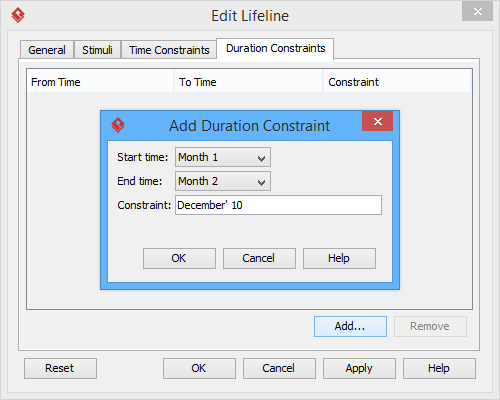
- Click OK to return to diagram.
Switching to compact view mode
To switch to compact view mode, right-click the frame and select View Mode > Compact from the popup menu.

The frame will be shown in compact mode.