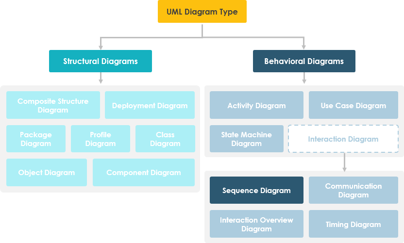
UML Sequence Diagrams are interaction diagrams that detail how operations are carried out. They capture the interaction between objects in the context of a collaboration. It depicts the objects and classes involved in the scenario and the sequence of messages exchanged between the objects needed to carry out the functionality of the scenario. Sequence diagrams are typically associated with use case realizations in the Logical View of the system under development.
A sequence diagram shows, as parallel vertical lines (lifelines), different processes or objects that live simultaneously, and, as horizontal arrows, the messages exchanged between them, in the order in which they occur. This allows the specification of simple runtime scenarios in a graphical manner.

Sequence Diagrams captures:
- the interaction that takes place in a collaboration that either realizes a use case or an operation (instance diagrams or generic diagrams)
- high-level interactions between user of the system and the system, between the system and other systems, or between subsystems (sometimes known as system sequence diagrams)
Other Related Sequence Diagram Articles