Use case diagram is a kind of UML diagram that enables you to model system functions (i.e. goals) as well as the actors that interact with those functions. You can draw use case diagrams in Visual Paradigm as well as to document the use case scenario of use cases using the flow-of-events editor. In this page, you will see how to draw use case diagram with the UML tool.
Creating a use case diagram
Perform the steps below to create a UML use case diagram in Visual Paradigm.
- Select Diagram > New from the application toolbar.
- In the New Diagram window, select Use Case Diagram.
- Click Next.
- Enter the diagram name and description. The Location field enables you to select a model to store the diagram.
- Click OK.
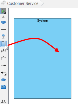
Drawing a system
To create a system in use case diagram, select System on the diagram toolbar and then click it on the diagram pane. Finally, name the newly created system when it is created.
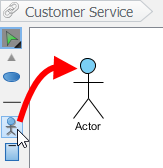
Drawing an actor
To draw an actor in use case diagram, select Actor on the diagram toolbar and then click it on the diagram pane. Finally, name the newly created actor when it is created.
Drawing a use case
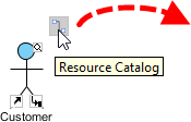
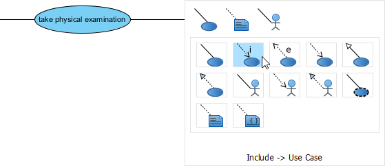
Besides creating a use case through diagram toolbar, you can also create it through Resource Catalog:
- Move the mouse over a source shape (e.g. an actor).
- Press on the Resource Catalog button and drag it out.
- Release the mouse button until it reaches your preferred place.
- Select Association -> Use Case from Resource Catalog.
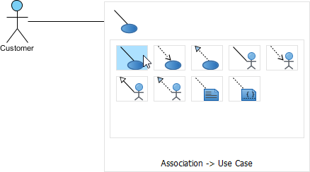
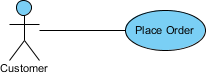
- The source shape and the newly created use case are connected. Finally, name the newly created use case.
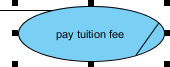
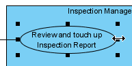
Line wrapping use case name
If a use case is too wide, you may resize it by dragging the filled selectors for a better outlook. As a result, the name of use case will be line-wrapped automatically.
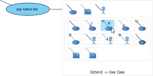
Drawing <<Extend>> relationship
To create an extend relationship, move the mouse over a use case, press and drag out its Resource Catalog button. Then, release the mouse button at the preferred place and select Extend -> Use Case from Resource Catalog. The use case with extension points and a newly created use case are connected. After you name the newly created use case, you can name the extension point.
Drawing <<Include>> relationship
To create an include relationship, move the mouse over a use case, press and drag out its Resource Catalog button. Then, release the mouse button at the preferred place and select Include -> Use Case from Resource Catalog. A new use case together with an include relationship is created. Finally, name the newly created use case.
Structuring use cases with package
You can organize use cases with package when there are many of them on the diagram.
Select Package on the diagram toolbar.
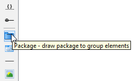
Drag the mouse to create a package surrounding those use cases.
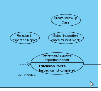
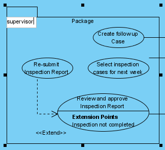
Finally, name the package.
Drawing business use case
The uml diagram tool also supports the representation of business actor and use case. To show an ordinary use case as business use case:
- Right click on a use case and select Model Element Properties > Business Model from the pop-up menu.
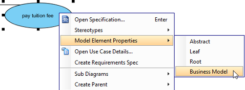
- After selected, an extra slash will be shown on the left edge of the use case.