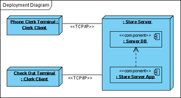
Deployment diagram is a kind of UML diagram that shows the physical aspects of an object-oriented system. It also shows the configuration of run time processing nodes and artifacts.
Creating deployment diagram
Perform the steps below to create a UML deployment diagram in Visual Paradigm.
- Select Diagram > New from the application toolbar.
- In the New Diagram window, select Deployment Diagram.
- Click Next.
- Enter the diagram name and description. The Location field enables you to select a model to store the diagram.
- Click OK.
Creating node
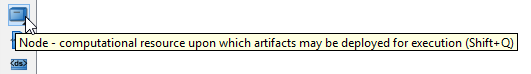
To create node in deployment diagram, click Node on the diagram toolbar and then click on the diagram.
Creating instance of node
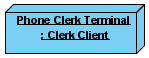
To create instance of node, click Instance Specification on the diagram toolbar and then click on the diagram.
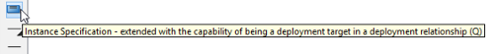
An instance specification will be created.
![]()
Selecting classifiers
To specify classifiers for an instance specification, right-click it and select Select Classifier > Select Classifier… from the pop-up menu.
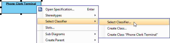
When the Instance Specification Specification window pops out, the Classifiers tab is opened by default. Click Add…. Then, select the classifier(s) in the popup window and click OK.
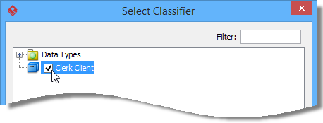
Click OK button to close the specification window. The selected classifiers are assigned to the instance specification.
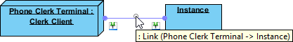
Creating link
To create link from instance specification:
- Move your mouse pointer over the source shape.
- Press on the Resource Catalog button and drag it out.
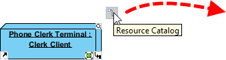
- Release the mouse button at the place where you want the instance specification to be created.
- Select Link -> Instance Specification from Resource Catalog.
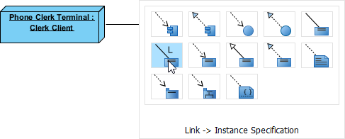
- A new instance specification will be created and is connected to the source shape. Enter its name and press Enter to confirm editing.
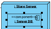
Creating instance of component
Similar to creating instance of node, you first create a component model element and then create an instance specification. However, this time assigns a component to the instance specification as classifier. After that the instance specification will be displayed as a component.
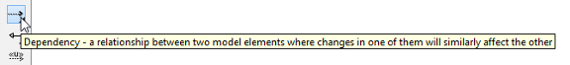
Creating dependency
To create dependency, click Dependency on the diagram toolbar.
Drag from the source shape, move the mouse over the target shape and then release the mouse button to create the dependency.
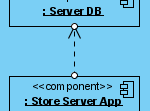
Continue to complete the diagram.