An object diagram in the Unified Modeling Language (UML), is a diagram that shows a complete or partial view of the structure of a modeled system at a specific time. In other words, it represents an instance of a class diagram which depicts a snapshot of the system at a particular moment. Object diagrams and class diagrams are closely related and use almost identical notation. Both diagrams are meant to visualize static structure of a system. While class diagrams show classes, object diagrams display instances of classes (objects). Object diagrams are more concrete than class diagrams. They are often used to provide examples or act as test cases for class diagrams. Only aspects of current interest in a model are typically shown on an object diagram.
Purpose of Object Diagram
The use of object diagrams is fairly limited, mainly to show examples of data structures.
- During the analysis phase of a project, you might create a class diagram to describe the structure of a system and then create a set of object diagrams as test cases to verify the accuracy and completeness of the class diagram.
- Before you create a class diagram, you might create an object diagram to discover facts about specific model elements and their links, or to illustrate specific examples of the classifiers that are required.
Other Related Object Diagram Articles
- What is Object Diagram?
- What is Class Diagram?
- What is UML?
- Why UML Modeling?
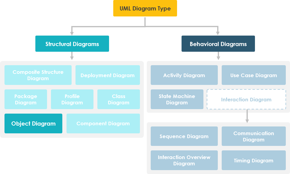
- Overview of the 14 UML Diagram Types