Each notation has its own meaning and semantic. For example, you use a use case to present users’ goals (system functions) but not how to achieve the goals. In order to model other aspects like the dynamic behavior of use case, you can elaborate a model element with a proper type of sub-diagram and contribute the details on the model element.
Creating a new sub diagram
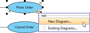
- Move the mouse over a shape, press its resource icon Sub Diagrams when it reveals and select New Diagram… from the pop-up menu.

Add a sub-diagram - In the New Diagram window, select the type of diagram to create. Note that the diagram types that are suitable for the selected shape are listed at the top of the window.
- Enter the diagram name.
- Click OK.
Note: Inserting a sub diagram on a model element, all child model elements of the sub diagram will also be attached.
Adding an existing diagram as sub diagram
- Move the mouse over a shape, press its resource icon Sub Diagrams when it reveals and select Existing Diagram… from the pop-up menu.
- In the Add Sub Diagrams window, select the diagram(s) to add as the sub-digram of the selected shape.
- Click OK.
Removing sub diagram
- Move the mouse over a shape, press its resource icon Sub Diagrams and select Manage… from the pop-up menu.
- In the specification window, select a sub diagram that you want it to be removed from the list and click Remove. When the Confirm Removedialog box pops out, click Yes button to confirm the deletion.
- Finally, click OK button to proceed.