A variety of shapes and model elements can be created by sketching a path directly on the diagram pane with dragging the right mouse button to form a gesture. For your convenience and quick creation, mouse gestures allow you to execute common commands and create UML models within all diagrams.
Drawing shapes
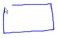
To start using a mouse gesture, press the right mouse button and drag it until finished drawing a shape.
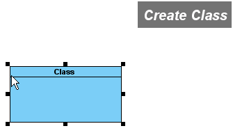
When the shape is done, release the mouse. After the shape is created, the action descriptionwill be shown on the top right corner of the diagram.
Creating Class member
You can learn how to create attribute and operation within the class in the following sub-sections.
Creating an attribute
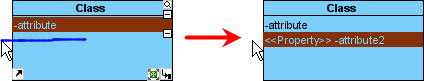
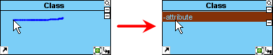
To create attribute, draw a line from the right to the left within the class. As a result, an attribute is created. _
If you draw the line until outside the class, an attribute with <<Property>> stereotype will be created.
Creating an operation
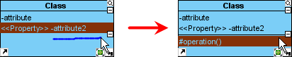
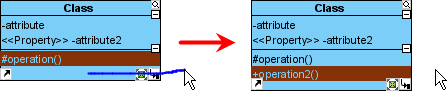
To create operation, draw a line from the left to the right within the class, an operation with protected visibility is created.
If draw the line until outside the class, a public operation will be created.
Connecting shapes
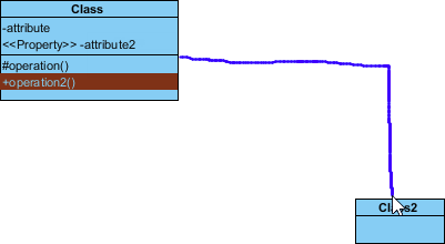
Draw a line from one shape to another.
After the mouse is released, a connector is created between two shapes.
Creating a new shape
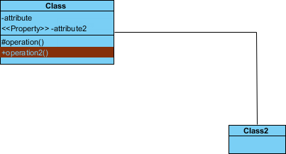
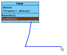
A new shape can also be created. To do so, draw a line from an existing shape to your preferred place.
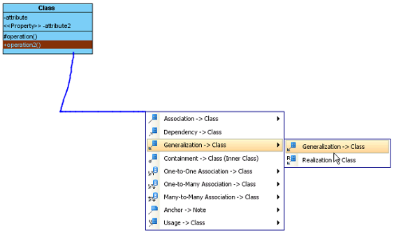
After the mouse is released, a pop-up menu will be shown. You can select your preferred type of connector and shape from the pop-up menu.
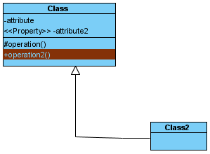
The two shapes with connector are created.
List of supported mouse gestures
General
Icon
Description
Layout diagram
Open diagram specification
Connect new shape
Connect existing shape
Close Diagram
Thumbnail view
Activity diagram
Icon
Description
Action
Activity
Decision Node
Initial Node/Finial Node (If there is no Initial Node, an Initial Node will be created. Else if there is no Final Node, a Final Node will be created.)
Activity diagram (UML 1.x)
Icon
Description
Action State
Sub-Activity
Swimlane
Horizontal Synchronization Bar
Vertical Synchronization Bar
Initial State/Final State (If there is no Initial State, an Initial State will be created. If there is no Final State, a Final State will be created.)
Business process diagram
Icon
Description
Sub-Process
Pool/Task
Horizontal Lane
Vertical Lane
Class diagram
Icon
Description
Sync. to ERD
Class
Package
Add attribute (Add an attribute to class. If mouse released outside the class, getter and setter property will be set to true.)
Add operation (Add an operation to class. If mouse released inside the class, visibility will be protected, otherwise it will be public.)
Communication diagram
Icon
Description
Sync. To Sequence Diagram
Lifeline
Actor
Package
Component diagram
Icon
Description
Component
Instance Specification
Package
Collaboration Use
Composite structure diagram
Icon
Description
Class
Interface
Collaboration
Collaboration Use
Data flow diagram
Icon
Description
Process
External Entity
Data Store
Deployment diagram
Icon
Description
Node
Component
Instance Specification
Package
EJB diagram
Icon
Description
Entity Bean
Message-Driven Bean
Session Bean
Package
Entity relationship diagram
Icon
Description
Sync. to Class Diagram
Entity
Add column
Interaction overview diagram
Icon
Description
Interaction
Decision Node
Initial Node/Final Node (If there is no Initial Node, an Initial Node will be created. Else if there is no Final Node, a Final Node will be created.)
Mind mapping diagram
Icon
Description
Node
The description of mouse gesture for mind mapping diagram
Object diagram
Icon
Description
Instance Specification
Class
Package
ORM diagram
Icon
Description
Sync. Classes -> Entities
Sync. Entities -> Classes
Class
Entity
Package
Overview diagram
Icon
Description
Diagram Overview
The description of mouse gesture for overview diagram
Package diagram
Icon
Description
Package
Sequence diagram
Icon
Description
Sync. to Communication Diagram
Lifeline
Actor
Alt
Loop
State machine diagram
Icon
Description
State
Submachine State
Initial Node/Final Node (If there is no Initial State, an Initial State will be created. Else if there is no Final State, a Final State will be created.)
State machine diagram (UML 1.x)
Icon
Description
State
Concurrent State
Submachine State
Horizontal Synchronization Bar
Vertical Synchronization Bar
Initial State/Final State (If there is no Initial State, an Initial State will be created. Else if there is no Final State, a Final State will be created.)
 _
_