Diagram element selection
When a number of diagram elements need to be selected simultaneously, diagram element selection supports this purpose. You can either click directly with hot keys or select a range of selection with the mouse. A specific type of diagram element(s) on a diagram can be selected as well.
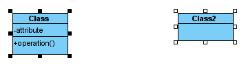
Selecting multiple shapes
Multiple shapes can be selected by either selecting a range of shapes with the mouse on diagram or clicking shapes with pressing hot keys.
Selecting a range of shapes with the mouse
- For selecting multiple shapes, drag them from corner to corner diagonally with the mouse.
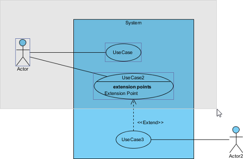
- After releasing the mouse, those shapes will be selected.
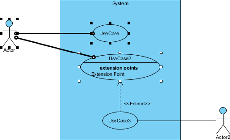
Clicking with pressing Ctrl/Shift key
Click a shape in advance and then click other shapes with pressing Ctrl or Shift key. As a result, those shapes will be selected.
Handi-Selection
In some cases, the shapes are too complicated and in more serious occasion, the whole diagram is extremely enormous that neither selecting a range of shapes with the mouse nor clicking shapes with pressing Ctrl or Shift key are the most suitable application. It is hard to drag the mouse on the large diagram, or is troublesome to click on many shapes. Using Handi-Selection is probably the best choice for you in this situation.
- Right click on the diagram’s background where is in the vicinity of those shapes you are going to select, select Handi-Selection and then select a scope for selecting shapes (i.e. above/ below/ left/ right) from the pop-up menu.
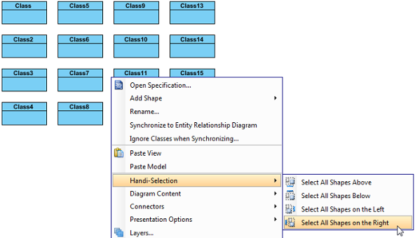
- As a result, all the shapes of the particular scope will be selected.
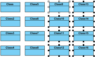
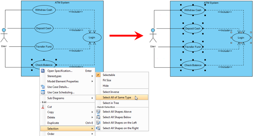
Selecting same type of shapes
When you want to select a few shapes of the same types on the diagram, right click on a shape and select Selection > Select All of Same Type from the pop-up menu. As a result, other shapes of same type as the shape you selected previously will be selected.
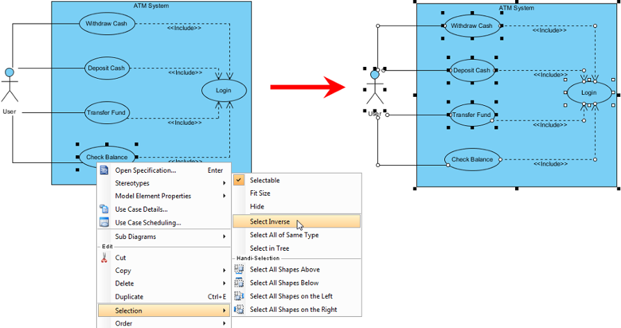
Inverse selection
Shapes can be selected inversely. Right click on a shape that you don’t want to be selected and select Selection > Select Inverse from the pop-up menu. As a result, all shapes will be selected except the shape you right clicked on previously.
Copy and paste
You can create a view of a model element by copying a view and pasting as view, while pasting as model creates a new model from the copied one.
Copying within Visual Paradigm
- Right click on the selected shape(s), select Copy > Copy within Visual Paradigm from the pop-up menu.
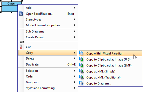
- After you switch to the destination diagram, right click on the diagram background and select either Paste View or Paste Model from the pop-up menu. The feature of Paste view refers to present the same model element in another view under a new context. The shape is pasted without creating model; while the feature of Paste Model refers to duplicate the shape and present it in a new view. The model will be copied and pasted on the diagram. The new model will be named with appending a sequential number.
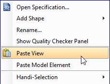
Paste the selected shape
Copying to clipboard as image (JPG)
- Right click on the selected shape(s) and select Copy > Copy to Clipboard as Image (JPG) from the pop-up menu.
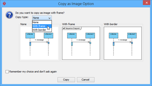
- When the Copy as Image Option dialog box pops out, select an option from the drop-down menu of Copy type. Click Copy button to proceed.
- You should select a destination document (e.g. MS Word) for pasting the copied shape(s) to do further description. After you switch to the destination document, right click on the desired place and select Paste from the pop-up menu.
- As a result, your selected shape(s) will be pasted on the destination document.
Copying to clipboard as image (EMF)
- Right click on the selected shape(s) and select Copy > Copy to Clipboard as Image (EMF) from the pop-up menu.
- When the Copy as Image Option dialog box pops out, select an option from the drop-down menu of Copy type. Click Copy button to proceed.
- EMF is a kind of scalable image which can be pasted on a document for further description. After you switch to the destination document, right click on a desired place and select Paste from the pop-up menu.
- As a result, your selected shape(s) will be pasted on the destination document.
Copying as XML
You can convert selected shapes into XML which contain the data of selected shapes in XML format. The XML data can then be imported into another project.
- Right click on the selected shapes and select Copy > Copy as XML from the pop-up menu.
- Open a text editor and create a new text file. Paste the XML there and save it as an XML file.
- After that, the file can be imported to another project by selecting File > Import > XML.
- When Import XML dialog box pops out, select the xml file path. Finally, click OK button to proceed.
Copying to Diagram
You can also copy the selected shape(s) to either a new diagram or an existing diagram. To copy to a diagram:
- Right-click on the selected shapes, select Copy > Copy to Diagram… from the pop-up menu.
- When the Copy to Diagram dialog box pops out, check Create new diagram if you want to paste to a new diagram or check Select an existing diagram if you want to paste to an existing diagram.
- Click Copy to button. As a result, the selected shape(s) will be duplicated on the selected diagram.
Duplicating
With the feature of duplicate, shapes can be duplicated on the same diagram instantly.
- Right click on the selected shape(s) and select Duplicate from the pop-up menu.
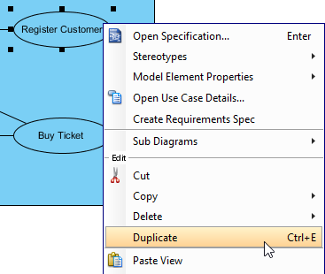
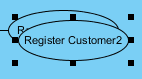
- As a result, the selected shape(s) will be duplicated.
Alignment guide
Alignment guide acts as a guide to help aligning shapes perfectly in the shortest period of time.
It is a dotted line that appears when you are moving the shape or resizing the shape within more than one shapes.
With the use of alignment guide, you can organize the diagram neatly with only little effort.
Arrange shapes in orderly arrangement
After dragging one shape from another shape, you will see a dotted line (the alignment guide) between the two shapes when you move either shape.
The Alignment Guide is here to help you to align the two shapes.
Take the following diagram as an example. If you move shape B vertically, you can see horizontal alignment guides appears on top, in the middle or at the bottom. You can choose to follow one of them depends on where you want to position shape B.
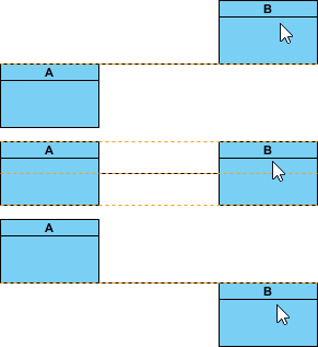
Similarly, when you move shape B horizontally, you can see vertical alignment guides appears on the left, in the middle and at the right.
With the help of alignment guide, you can produce a neat diagram with ease.
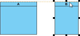
Other than moving the shape, alignment guide also appears when you resize the shape.
Let’s take a look at the diagram below. If you want to resize shape B to produce equal height as shape A. The alignment guide can guide you to achieve this.
Evenly distribute the spacing among shapes
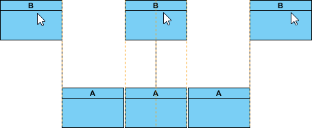
If you want the spacing among shape B and C equals to shape A and B, simply move shape C parallel to shape B, an additional dotted line at the bottom of the diagram (as pointed by red arrows) represents equal spacing among shape A and B as well as shape B and C.
Therefore, this additional dotted line acts as a hint that help you to create equal spacing efficiently and precisely.
On the contrary, the additional dotted line will not appear if the spacing are not equal.
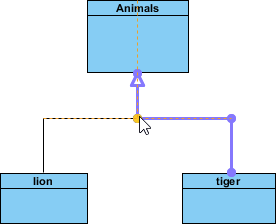
Layout generalization hierarchy with ease
Alignment guide is very useful in producing a neat layout of generalization hierarchy as well.
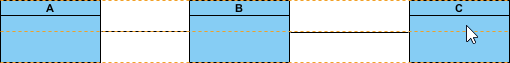
While it’s nice to present super-class and its sub-classes in hierarchical form, it’s uneasy to route the generalization connectors perfectly to make the hierarchy looks neat and tidy. Sometimes, the connectors are either partially overlapped or entirely detached from each other. All these affect the harmony of the design and may even reduce readability.
Alignment guide is here to help. By dragging on a generalization connector, you can make its turning point snap to a position that aligns with another generalization horizontally. Therefore, you can produce a neat hierarchy effortlessly with the aid of alignment guide.
Turn off the Alignment guide
In case users want to disable the Alignment guide function, here are some simple steps:
- Select Window > Application Options… from the toolbar.
- Enter guide in the search field of the Application Options window to locate the option.
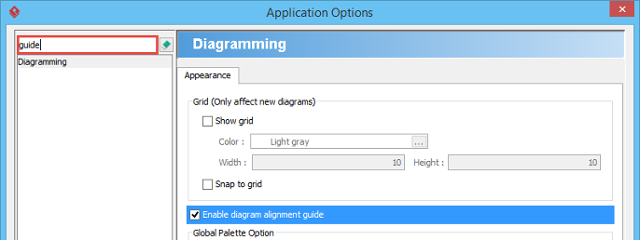
- In the Appearance tab of the Diagramming page, uncheck Enable diagram alignment guide.
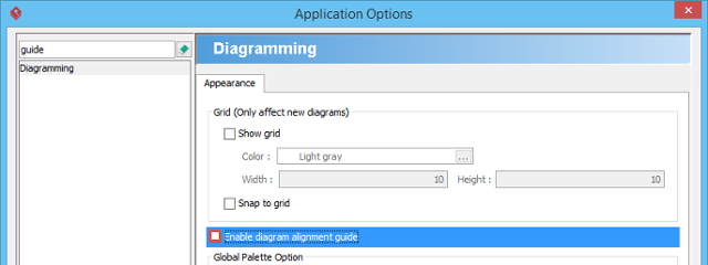
- Click OK to confirm the setting.
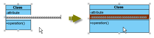
Fit shape size
In some cases, shapes are found oversized. For better presentation, you may need to resize them smaller. Fit size can help you to adjust shapes into the smallest size based on their content, such as the name of shape. The size of shapes can be fixed either manually or automatically.
Note: The size of shapes can be fixed automatically by right clicking on the diagram’s background and checking Diagram Content> Auto Fit Shapes Size.
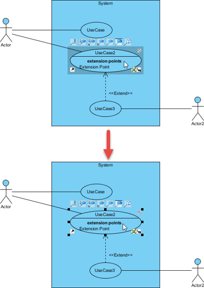
Fit selected shapes size
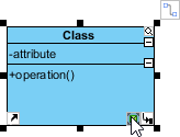
To adjust a shape size, move the mouse on a shape and fit size resource centric interface will be shown. Click Fit Size resource icon at the bottom of the shape.
To fit several shapes’ size, select those shapes, right click on a selected shape and then select Selection > Fit Size from the pop-up menu.

Each shape will be adjusted to its fit size in accordance with its content, instead of fixing all selected shapes into the exactly same size.
Check/uncheck automatic fit shape size mode
You can check/ uncheck the Auto Fit Shapes Size on diagram to make all the shapes on the diagram to be fitted size automatically. To do so, right click on the diagram’s background, select Diagram Content > Auto Fit Shapes Size from the pop-up menu.
All the shapes are subsequently fitted size and they will become non-sizable.
If the content of shape is changed, the shape itself will be resized automatically.
You can also check Auto Fit Size for future usage.
- Select Window > Project Options… from the toolbar to open the Project Options window.
- In the Project Options window, choose the Diagramming category, select the Shape tab and check Auto fit size (diagram-based).