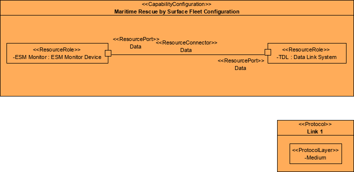
The networks and pathways documented in a P3 Viewpoint represent the physical implementation of the logical flows identified in an L2, Logical Scenario, or L3, Node Interactions View.
The P3 Viewpoint focuses on the physical characteristics of each link by specifying attributes. An example of this might be the geographic location and layout of network components such as routers, switches, amplifiers, and repeaters. Attributes such as capacities (e.g. bandwidth, throughput), frequencies used, security encryption methods used and other descriptive information are also included. The P3 View encompasses the NSV-2b and 2c views from NAFv3.1, which define the communications links between systems.
The P3 Viewpoint differs from that of P2 in that it only features physical architectures, software, and artifacts (as systems) – i.e. P3 does not feature any organizational resources. P3 also provides a great deal more technical detail than P2, specifying the protocols implemented by systems and used by the connections between those systems.
Usage
The intended usage of the P3 includes:
- Interface specification.
- Identification of applicable protocols.
- Description of system communication paths.
- Bandwidth and capacity analysis.
- Detailed definition of data flows.
Creating a Resource Connectivity diagram
To create a Resource Connectivity diagram:
- Click on Resource Connectivity in the Action Artifact area, and then select Create New Diagram.
- Type the diagram name and press Enter.
- A blank diagram is created and you can start constructing the view. Reuse resource types (ResourceArchitecture / System / CapabilityConfiguration / Organization / Person / Post / Responsibility / Project / NaturalResource / ResourceArtifact / Software / Technology) (recommended) through dragging and dropping them from the Model Explorer. Resource types are defined in P1.
- Create ResourceConnectors between ResourceRoles. If ResourceRoles weren’t yet defined in P1 and P2, you can create them in this view.
Creating an Internal Resources Flow table
The Internal Resources Flow table specifies the resource flows among resources. Unlike P2, P3 focuses on the role-based flows.
To create an Internal Resources Flow table:
- Click on Internal Resources Flow in the Action Artifact area to open the Resource Exchanges table.
- This opens the Resource Exchanges table with ResourceExchanges listed.
- For each of the ResourceExchanges:
- Create a new ResourceExchanges by clicking on the New Resource Exchange above the table.
- This creates a new row of ResourceExchanges. Enter its name.
- Select the ResourceConnector that the ResourceExchange realizes. The ResourceConnectors are defined in the Resource Connectivity diagram.
- Select the items involved in resource exchange.
- Optionally fill-in the attributes of resource exchanges.
The emphasis in this view is on the logical and operational characteristics of the resource being exchanged. It is important to note that P3 is not intended to be an exhaustive listing of all the details contained in every resource exchange of every node associated with the architecture in question. Rather, this product is intended to capture the most important aspects of selected resource exchanges. The table below shows an example of the relevant information content.
| Data Description | Nature of Transaction | Performance Attributes | Information Assurance | Security |
|
|
|
|
|
Resource Connectivity

Internal Resource Flow