The P2 Viewpoint links together the operational and physical architecture viewpoints by depicting how types of Resource are structured and interact to realize the logical architecture specified in L2, Logical Scenario. The P2 Viewpoint may represent the realization of a requirement specified in an L2 (i.e. in a “to-be” architecture) and so there may be many alternative Resource viewpoint suites that could realize the operational requirement. Alternatively, in an “as-is” architecture, an L2 may just be a simplified, logical representation of the P2 Viewpoint to allow communication of key information flows to non-technical stakeholders.
Usage
The intended usage of the P2 includes:
- Definition of system concepts.
- Definition of system options.
- Human – System interactions.
- Typical Organization structures.
- Interface requirements capture.
- Capability integration planning.
- System integration management.
- Operational planning (capability configuration definition).
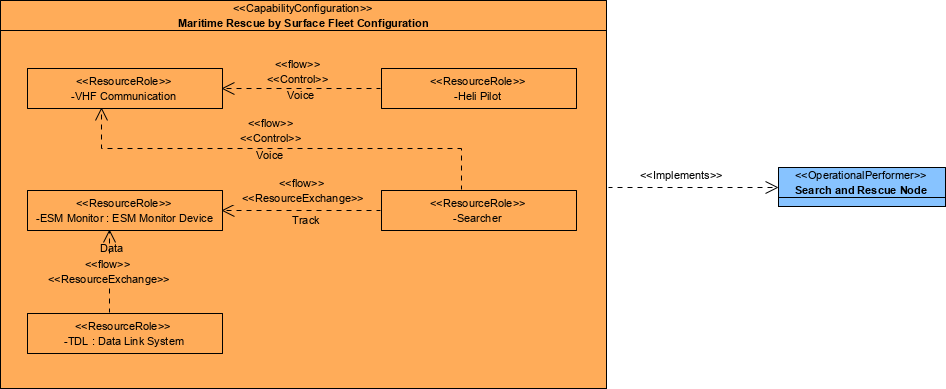
Creating a Resource Structure diagram
To create a Resource Structure diagram:
- Click on Resource Structure in the Action Artifact area, and then select Create New Diagram.
- Type the diagram name and press Enter.
- A blank diagram is created and you can start constructing the view. Reuse resource types (ResourceArchitecture / System / CapabilityConfiguration / Organization / Person / Post / Responsibility / Project / NaturalResource / ResourceArtifact / Software / Technology) (recommended) through dragging and dropping them from the Model Explorer. The resource types are defined in R1.
- Draw the resource flows among the resource types by creating ResourceExchanges between them.
The resource flow can be specified with the Resource Flow table.
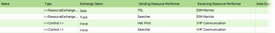
Creating a Resource Flow table
The P2 Resource Flow table identifies the interaction of resources. It details resource exchanges by identifying which resource exchange what information, with whom, why the information is necessary, and the key attributes of the associated resources.
To create a Resource Flow table:
- Click on Resource Flow in the Action Artifact area to open the Resource Flow table.
- This opens the Resource Flow table with ResourceExchanges, Command and Control listed.
- For each of the ResourceExchanges, Command and Control:
- Enter its ID
- Select the items involved in operational exchange.
Resource Structure
Resources Flow