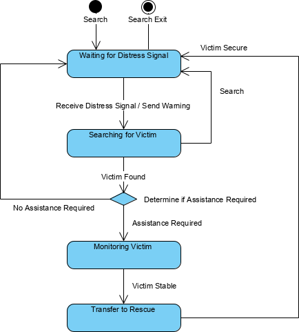
The L5 Viewpoint specifies the typical states a node may have and the possible transitions between those states (i.e. changes of state). Triggers for state changes may also be defined. Actions may be associated with a given state or with the transition between states in response to stimuli (e.g. triggers and events).
Usage
The intended usage of the L5 includes:
- Analysis of business events.
- Behavioural analysis.
- Identification of constraints.
Creating a Logical States diagram
To create a Logical States diagram:
- Click on Logical States in the Action Artifact area, and then select Create New Diagram.
- You are creating a table for managing the state diagrams. Type a name for the table. You can create multiple tables based on different contexts (e.g. by phases, purposes, etc).
- This opens a table where you can create and manage state diagrams. Click on New Logical State Machines Definition above the table to create a new row.
- Under the first column, select the context to create a state diagram, which can be an OperationalPerformer or OperationalArchitecture.
- Under the second column, create the state diagram(s). The diagram created will be added to the selected context element as a sub-diagram.