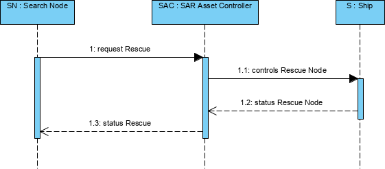
Operational Event-Trace Descriptions, sometimes called sequence diagrams, event scenarios or timing diagrams, allow the tracing of interactions between nodes in a scenario or critical sequence of events. The node interactions usually correspond to flows of information but may describe flows of energy, material or people specified in the L2, Logical Scenario.
Usage
The intended usage of the L6 includes:
- Analysis of operational events.
- Sequences of interactions between nodes.
- Behavioural analysis.
- Identification of non-functional user requirements.
- Operational test scenarios.
Creating a Logical Sequence diagram
To create a Logical Sequence diagram:
- Click on Logical Sequence in the Action Artifact area, and then select Create New Diagram.
- Type the diagram name and press Enter.
- A blank diagram is created and you can start constructing the view.