An SV-1 specifies the composition and interaction of resources.
The SV-1 links together the operational and systems architecture models by depicting how Resources are structured and interact to realize the logical architecture specified in an OV-2 Operational Resource Flow Description. A SV-1 may represent the realization of a requirement specified in an OV-2 Operational Resource Flow Description (i.e., in a “To-Be” architecture), and so there may be many alternative SV models that could realize the operational requirement.
A System Resource Flow is a simplified representation of a pathway or network pattern, usually depicted graphically as a connector (i.e., a line with possible amplifying information). The SV-1 depicts all System Resource Flows between Systems that are of interest. Note that Resource Flows between Systems may be further specified in detail in SV-2 Systems Resource Flow Description and SV-6 Systems Resource Flow Matrix.
Sub-System assemblies may be identified in SV-1 to any level (i.e., depth) of decomposition the architect sees fit. SV-1 may also identify the Physical Assets (e.g., Platforms) at which Resources are deployed, and optionally overlay Operational Activities and Locations that utilize those Resources. In many cases, an operational activity and locations depicted in an OV-2 Operational Resource Flow Description model may well be the logical representation of the resource that is shown in SV-1.
Usage
The intended usage of the SV-1 includes:
- Definition of System concepts.
- Definition of System options.
- System Resource Flow requirements capture.
- Capability integration planning.
- System integration management.
- Operational planning (capability and performer definition).
Product Description
A primary purpose of a SV-1 DoDAF-described Model is to show resource structure, i.e., identify the primary sub-systems, performer and activities (functions) and their interactions. SV-1 contributes to users’ understanding of the structural characteristics of the capability.
The physical resources contributing to a capability are either an organizational resource or a physical asset, i.e., a system cannot contribute alone (it must be hosted on a physical asset used by an organizational resource of both). Organizational aspects can now be shown on SV-1 (e.g., who uses System). Resource structures may be identified in SV-1 to any level (i.e., depth) of decomposition the architect sees fit.
A SV-1 can optionally be annotated with Operational Activities, Capabilities, and/or Locations originally specified in OV-2 Operational Resource Flow Description model. In this way, traceability can be established from the logical OV structure to the physical System Viewpoint structure. If possible, a SV-1 shows Systems, Physical Assets and System interfaces for the entire Architectural Description on the same diagram. If a single SV-1 is not possible, the resource of interest should be decomposed into multiple SV-1 models.
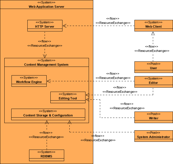
Creating a Systems Interface Description
To create a Systems Interface Description (diagram):
- Click on Systems Interface Description in the Action Artifact area, and then select Create New Diagram.
- Type the diagram name and press Enter.
- A blank diagram is created and you can start constructing the view.
- Draw the resource types – ResourceArchitecture / System / CapabilityConfiguration / Organization / Person / Post / Responsibility / Project / NaturalResource / ResourceArtifact / Software / Technology.
- Draw the resource flows among the resource types by creating ResourceExchanges / Commands / Controls between them.