The SV-10c provides a time-ordered examination of the interactions between functional resources. Each event-trace diagram should have an accompanying description that defines a particular scenario or situation.
The SV-10c is valuable for moving to the next level of detail from the initial solution design, to help define a sequence of functions and system data interfaces, and to ensure that each participating resource or System Port role has the necessary information it needs, at the right time, to perform its assigned functionality.
Usage
The intended usage of the SV-10c includes:
- Analysis of resource events impacting operation.
- Behavioral analysis.
- Identification of non-functional system requirements.
Product Description
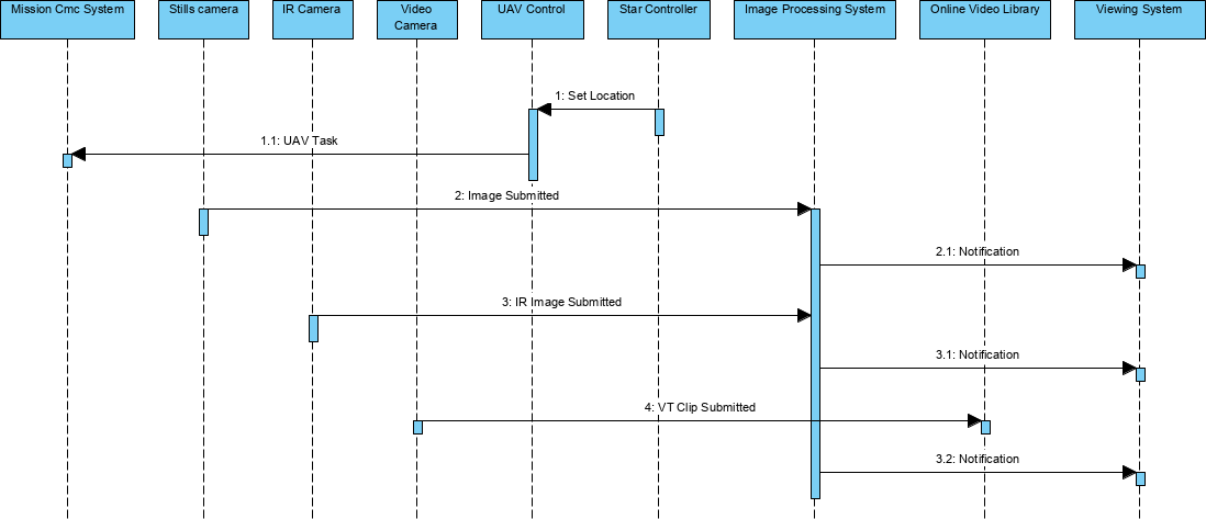
The SV-10c specifies the sequence in which Resource Flow elements are exchanged in the context of a resource or System Port.
The items across the top of the sequence diagram are usages of resources or resource ports. The lifelines are depicted as vertical lines descending from the resources and ports.
Arrows between the lifelines represent exchanges of messages (data), materiel, energy or human resources. The direction of the event lines represents the flow of information from one resource/port to another. The System Event-Trace Description provides a time-ordered examination of the Resource Flow elements exchanged between participating resources (external and internal) or system ports. Each Event/Trace diagram should have an accompanying description that defines a particular scenario or situation.
The SV-10c is typically used in conjunction with the SV-10b Systems State Transition Description to describe the dynamic behavior of resources. The data content of messages that connect Resource Flows in a SV-10c may be related with Resource Flows (the interactions in the SV-1 Systems Interface Description and SV-3 Systems-Systems Matrix), Resource Flows (the data in the SV-4 Systems Functionality Description and SV-6 Systems Resource Flow Matrix) and entities (in DIV-3 Physical Data Model) modeled in other models.
Creating a Systems Event-Trace Description
To create a Systems Event-Trace Description diagram:
- Click on Systems Event-Trace Description in the Action Artifact area, and then select Create New Diagram.
- Type the diagram name and press Enter.
- A blank diagram is created and you can start constructing the view.