The SV-10b is a graphical method of describing a resource (or system function) response to various events by changing its state. The diagram basically represents the sets of events to which the resources in the Activities respond (by taking an action to move to a new state) as a function of its current state. Each transition specifies an event and an action.
The explicit time sequencing of service functions in response to external and internal events is not fully expressed in SV-4 Systems Functionality Description. The SV-10b can be used to describe the explicit sequencing of the functions. Alternatively, SV-10b can be used to reflect explicit sequencing of the actions internal to a single function, or the sequencing of system functions with respect to a specific resource.
Usage
The intended usage of the SV-10b includes:
- Definition of states, events and state transitions (behavioral modeling).
- Identification of constraints.
Product Description
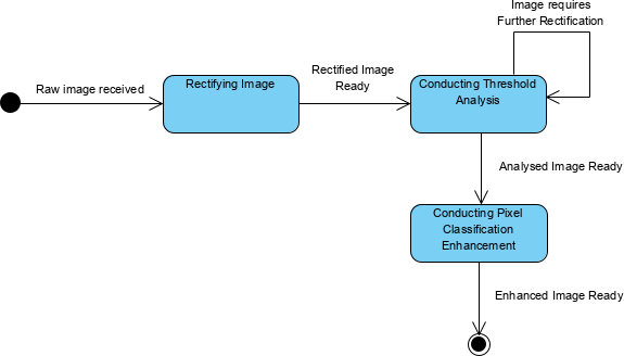
The SV-10b relates events to resource states and describes the transition from one state to another.
Composing state transitions provides a model of states known as a statechart.
The SV-10b models state transitions from a resource perspective, with a focus on how the resource responds to stimuli (e.g., triggers and events). As in the OV-6b Operational State Transition Description, these responses may differ depending upon the rule set or conditions that apply as well as the resource’s state at the time the stimuli are received. A change of state is called a transition. Each transition specifies the response based on a specific event and the current state. Actions may be associated with a given state or with the transition between states. A state and its associated actions specify the response of a resource or function, to events. When an event occurs, the next state may vary depending on the current state (and its associated action), the event, and the rule set or guard conditions.
Creating a Systems State Transition Description (diagram)
To create a Systems State Transition Description diagram:
- Click on Systems State Transition Description in the Action Artifact area, and then select Create New Diagram.
- You are creating a table for managing the state diagrams. Type a name for the table. You can create multiple tables based on different contexts (e.g. by phases, purposes, etc).
- This opens a table where you can create and manage state diagrams. Click on New Resource State Machines Definition above the table to create a new row.
- Under the first column, select the context to create state diagram, which can be ResourceArchitecture, System, CapabilityConfiguration, Organization, Person, Post, Responsibility, Project, NaturalResource, ResourceArtifact, Software or Technology.
- Under the second column, create the state diagram(s). The diagram created will be added to the selected context element as a sub-diagram.