An SV-4 specifies the human and system functionality carried out by all types of Resources.
The primary purposes of the SV-4 are to:
- Specify the behavior of resources in the architecture.
- Develop a clear description of the necessary data flows that are input (consumed) by an output (produced) by each resource.
- Ensure that the functional connectivity is complete (i.e., that a resource’s required inputs are all satisfied).
The Functionality Description provides detailed information regarding the:
- Allocation of functions to resources.
- Flow of resources between functions.
The SV-4 is the Systems Viewpoint model counterpart to the OV-5b Activity Model of the Operational Viewpoint.
Usage
The intended usage of the SV-4 includes:
- Description of task workflow.
- Identification of functional system requirements.
- Functional decomposition of systems.
- Relate human and system functions.
Product Description
The SV-4 is used to specify the functionality of resources in the architecture (in this case, functional resources, systems, performer and capabilities). The SV-4 is the behavioral counterpart to the SV-1 Systems Interface Description (in the same way that OV-5b Operational Activity Model is the behavioral counterpart to OV-2 Operational Resource Flow Matrix).
The scope of this model may be capability wide, without regard to which resources perform which functions, or it may be resource-specific. Variations may focus on intra- or inter-resource data flows, or may simply allocate functions to resources.
There are two diagrams to depict activity models, as explained below.
Systems Functionality Description
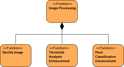
The Taxonomic Functional Hierarchy shows a decomposition of functions depicted in a tree structure and is typically used where tasks are concurrent but dependent, such as a production line, for example.
Systems Functionality Flow Description
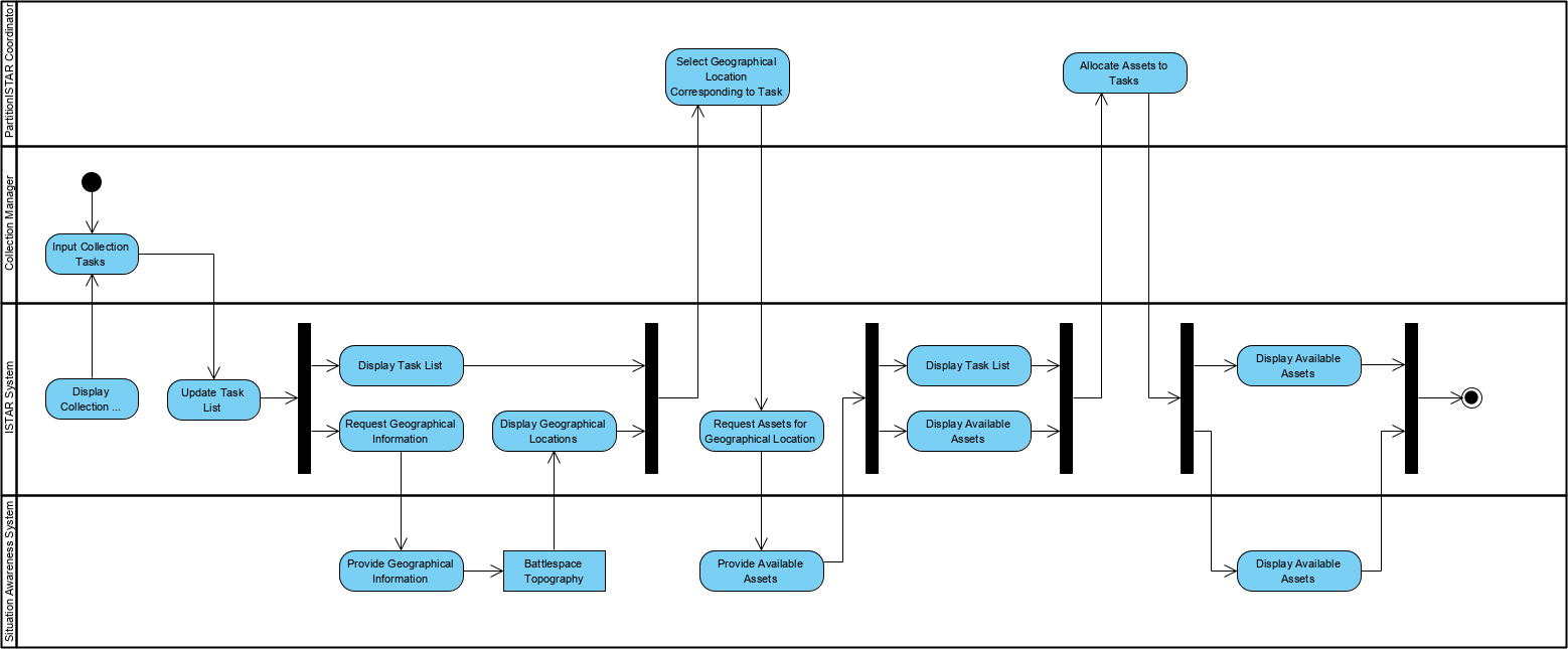
The functional flow diagram shows functions connected by data and control flow arrows.
The Taxonomic Functional Hierarchy may be particularly useful in capability-based procurement where it is necessary to model the functions that are associated with particular capability (see SV-5).
Within an Architectural Description, the SV-4 documents system functions, the Resource Flows between those functions, the internal system data repositories or system data stores, and the external producers and consumers for the system data flow, but not those external to the Architectural Description scope. They may also show how users behave in relation to those systems.
Creating a Systems Functionality Description
To create a Systems Functionality Description:
- Click on Systems Functionality Description in the Action Artifact area, and then select Create New Diagram.
- Type the diagram name and press Enter.
- A blank diagram is created and you can start constructing the view. Create Functions through the tool under the diagram toolbar.
Creating a Systems Functionality Flow Description (diagram)
To create a Systems Functionality Flow Description (diagram):
- Click on Systems Functionality Flow Description in the Action Artifact area, and then select Create New Diagram.
- Type the diagram name and press Enter.
- A blank diagram is created and you can start constructing the view. Create the activity flows with FunctionActions and other flow elements (e.g. Control Flows, Decision Nodes, etc).
Systems Functionality Description

Systems Functionality Flow Description
